PID stands for Proportional, Integral and Derivative control. This is a control system algorithm. It is basically a feedback mechanism which can predict error by comparing an output variable with a reference value and apply a correction based on proportional, integral and derivative terms. The algorithm aims to predict and minimise error in an output variable. The algorithm is usually implemented by an electronic controller and it can be implemented in several ways in a programming language. There are even many open-source libraries available which implement the PID algorithm. The PID algorithm is widely used in the industrial control systems like in the robotic arms and assembly lines.
The PID control system can be used for a line follower as well. The typical line followers have jerky movement due to sudden nature of line detection and path correction. By applying PID control algorithm, the line follower can be made to move smoothly along the line. This also allows the line follower to move faster and follow its path with much pace.
The PID controlled line follower designed in this tutorial is built on Arduino UNO and has the algorithm implemented within the Arduino Sketch. The hardware design of the line follower is same as that of any other typical line follower robot. The electronic circuitry of the robot consists of the Arduino board, IR sensor array and L293D motor driver IC coupled with two geared DC motors. The robot is powered by a 12V battery and is programmed to instantly start following its path once it is powered on.

Fig. 1: Prototype of Arduino based PID Line Follower Robot
Components Required –

Fig. 2: List of components required for Arduino based PID Line Follower Robot
The following components will be required for designing the sensor array –

Fig. 3: List of components required for IR Sensor Module
Block Diagram –

Fig. 4: Block Diagram of Arduino based PID Line Follower Robot
Circuit Connections –
The PID algorithm for controlling the line follower is implemented within the Arduino Sketch. It is the Arduino board that controls the motion of the line follower. The sensor circuit as well the motor driver circuit are interfaced with the Arduino board. The electronic circuit controlling the robot has the following building blocks –
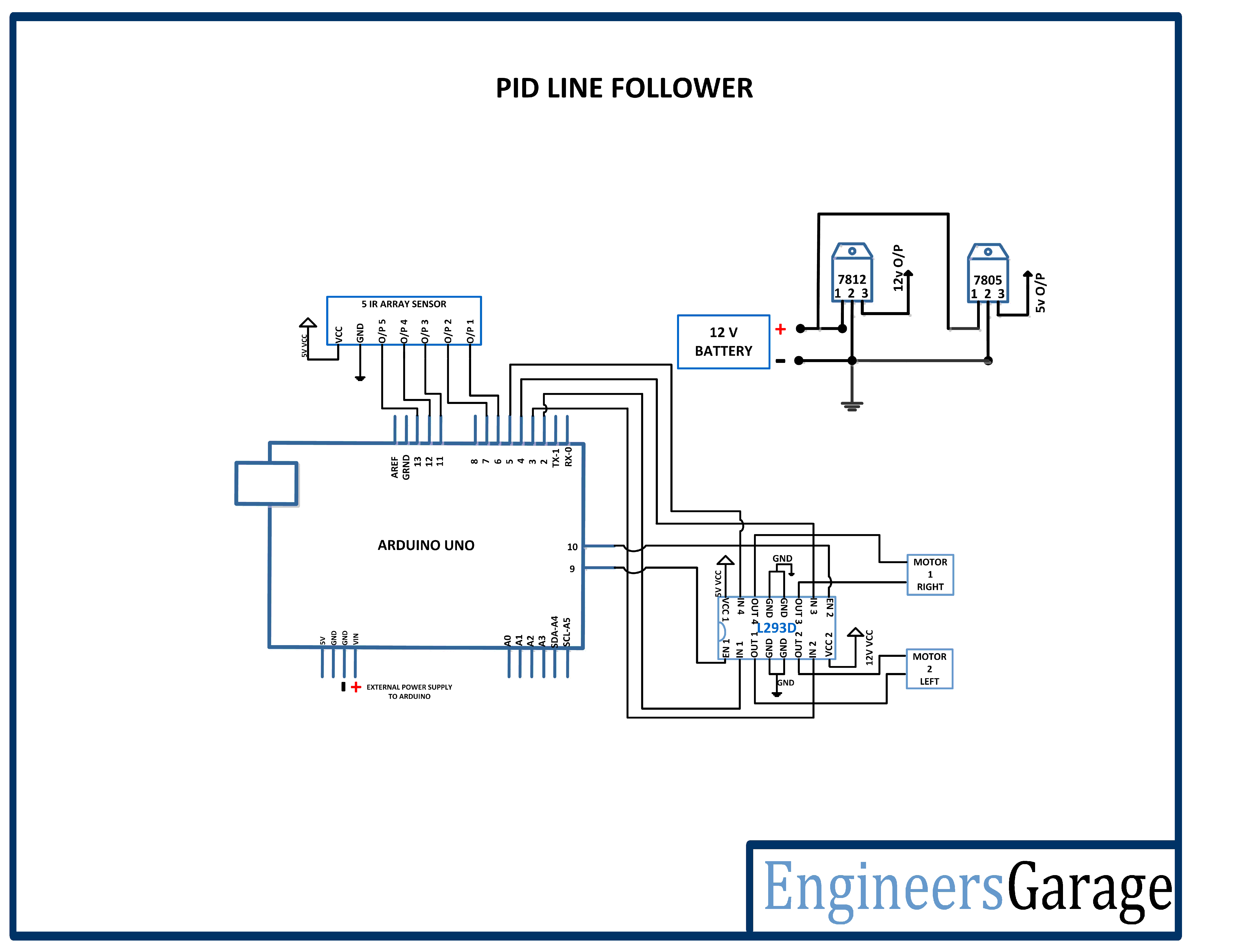
Power Supply – In the circuit, Arduino board and IR sensor array need a 5V regulated DC for their operation while the motor driver IC needs 12V DC. A 12V NIMH battery is used as the primary source of power. The supply from the battery is regulated to 5V and 12V using 7805 and 7812 ICs. The pin 1 of both the voltage regulator ICs is connected to the anode of the battery and pin 2 of both ICs is connected to ground.
The respective voltage outputs are drawn from pin 3 of the respective voltage regulator ICs. An LED along with a 10K Ω pull-up resistor is also connected between common ground and output pin to get a visual hint of supply continuity. Despite using 12V battery, 7812 is used to provide a regulated and stable supply to the motor driver IC. The DC motors cannot be directly connected to the battery as they can only be controlled by the motor driver IC and the motor driver IC itself need a regulated power input.
Arduino UNO – Arduino UNO is one of the most popular prototyping boards. It is used frequently in robotic applications as it is small in size and packed with rich features. The board comes with built-in Arduino boot loader. It is an Atmega 328 based controller board which has 14 GPIO pins, 6 PWM pins, 6 Analog inputs and on board UART, SPI and TWI interfaces. In this project, 5 GPIO pins of the board are utilized to connect the IR sensors and 4 GPIO pins are used to interface L293D motor driver IC.
L293D DC Motor Driver IC – The L293D is a dual H-bridge motor driver integrated circuit (IC). The Motor drivers act as current amplifiers since they take a low-current control signal and provide a higher-current signal. This higher current signal is used to drive the motors. It has 16 pins with following pin configuration:

Fig. 5: Table listing pin configuration of L293D Motor Driver IC
For robot’s motion, there are two DC motors used. The DC motors are interfaced between pins 3 and 6 and pins 14 and 11 of one of the motor driver IC.
The L293D IC controls the DC Motors according to the following truth tables:

Fig. 6: Truth Table of L293D Motor Driver IC
The pin 4, 5, 13 and 12 of the L293D IC are grounded while pins 1, 16 and 9 are connected to 5V DC and pin 8 is connected to 12V DC. The pins 15, 2, 7 and 10 of this motor driver IC are connected to pins 5, 2, 3 and 4 of the Arduino board. The DC motor attached to right wheel is connected to pins 11 and 14 while motor attached to left wheel is connected to pins 3 and 6 of the motor driver IC.
The pins 15, 2, 7 and 10 are input signal pins of the motor driver IC. These are connected to Arduino pins. On changing digital logic at the Arduino pins, the logic at the input pins of the motor driver IC is also changed. As summarized in the tables above, the direction of rotation of the DC motors depends upon the digital logic at the input pins of the motor driver IC.
Geared DC Motors – In this robot, 12V geared DC motors are attached to the wheels. Geared DC motors are available with wide range of RPM and Torque, which allow a robot to move based on the control signal it receives from the motor driver IC.
IR sensor array – The line follower is designed to follow black strips of line. For this, a sensor which can detect the colour of underneath surface is required. The IR sensors can detect the colour of underneath surface based on reflective/non-reflective indirect incidence. The IR LEDs emit IR radiation which in normal state gets reflected back from the white surface around the black line.
The reflected radiations are detected by the photodiodes. But when the IR radiation falls on a black line, it gets absorbed completely by the black colour and hence there is no reflection of the IR radiation back to the sensor module. This way, an IR sensor module detects the black strips. The IR sensors are available with analog output as well as digital output. In this robot, the sensor module is designed using the IR sensors having digital output.

Fig. 7: Circuit Diagram of IR Sensor Array
The IR sensor modules are constructed by the following components –
a) IR Transmitters – The IR LEDs are used as IR transmitters in the circuit. An IR LED is a type of LED which emits light in the Infra-Red frequency range. The infra-red radiations are not visible to the human eye but can be seen by the lenses of a camera. Operationally, IR LEDs are not much different from normal LEDs. They also need a 3V DC for biasing and consume 20 mA current. They also need to be connected with pull-up resistor in a circuit. In the module, IR LEDs are connected with 470 ohm pull-up resistors.
b) IR Receivers – The photodiodes are used as IR receivers in the circuit. A photodiode is a type of diode which gets forward biased when light is incident on it. It has a high resistance when no light is falling on it. When the intensity of light incident on it increases, it starts getting forward biased and current starts flowing through it. So, when light is incident on it, its resistance decreases and there is less voltage drop across it. When light is not incident on it, its resistance increases and there is higher voltage drop across it. The photodiode looks exactly like an LED and may have a dark blue or black film on the outer casing. The photodiodes are used in reverse bias configuration in the circuit.
Variable resistor – The variable resistors are used in the sensor circuit to form a resistive voltage divider. The VCC is applied at the variable resistor side, so the output from the voltage divider is proportional to the resistance of the variable resistor and is inversely proportional to the resistance of the respective photodiode. The use of variable resistor allows calibrating the sensor circuit to properly detect the black strips.
LM358M OPAM – The LM358M is used to add operational amplifiers in the circuit. The LM358M is a general purpose Dual Operational Amplifier (Op-Amp). The OPAM are used as negative voltage comparators in the circuit. The LM358M is an 8-pin IC with following pin configuration –

Fig. 8: Table listing pin configuration of LM358M OPAMP IC
The IC is used in single supply configuration in the circuit. For five IR sensor modules, three LM358M ICs are used as each IC provides two OPAM circuits. Any General Purpose Op-amp with similar gain and operating voltages like the LM324M can also be used.

Fig. 9: Pin Diagram of LM358 OPAMP IC
For making the sensor module, the IR transmitters are connected in series with pull-up resistors of 470 ohm between VCC and ground in forward bias configuration. The IR receivers are connected in series with variable resistors between VCC and ground in reverse bias configuration forming a voltage divider circuit.
The output from the IR receivers (photodiodes) are drawn from the junction of cathode terminals of the IR receiver and variable resistors. Such five pairs of IR receiver and transmitter are connected between VCC and ground to form an IR sensor array. The output from the five IR receivers is connected to the pins 6, 7, 11, 12 and 13 of the Arduino UNO via OPAM comparators.

Fig. 10: Image of IR Sensor Array

Fig. 11: Image showing IR Sensor Array Mounted on Robot
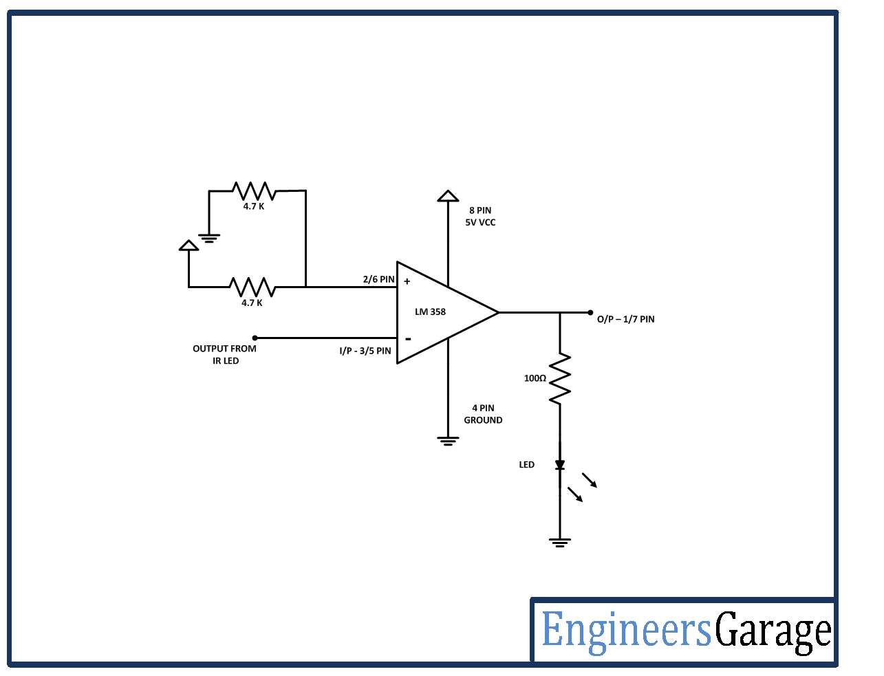
For proper digital output from the IR receivers, the output from the IR receivers is first connected to the inverting input of an operational amplifier. The non-inverting input of the operational amplifier is provided a reference voltage half the HIGH digital logic (5V for the microcontroller circuit) by connecting two 4.7 K ohm resistors between VCC and ground and connecting the resistive junction with the non-inverting input. Then the output pin of the OPAM is connected to the microcontroller pin.
The same is done for all the five IR sensors. The operational amplifier is used in the circuit for comparison of the output of IR receiver with the HIGH and LOW digital logic where the reference voltage is set as the half of the HIGH digital logic. So, each OPAM works as a voltage comparator to output a digital logic at the corresponding Arduino pin.
The OPAM is used as negative voltage comparator in the circuit as the reference voltage is set at the non-inverting input and the input voltage from the IR receiver is applied at the inverting input. In such configuration, when the voltage at the inverting input is lower than the reference voltage at the non-inverting input, the output of the OPAM is HIGH while when the voltage at the inverting input of the OPAM is higher than the reference voltage at the non-inverting input, the output of the OPAM is LOW.

Fig. 12: Image showing OPAM Circuit assembled on Breadboard
The input from the IR sensor module is drawn from the junction of 10K variable resistor and the IR receiver. When the IR radiation from the IR transmitter is incident on white surface, it is reflected back and absorbed by the IR receiver (Photodiode). This reduces the resistance of the IR receiver, and there is less voltage drop across it. As a result, more voltage is dropped across the variable resistor which is output by the sensor. So there is less voltage output by the sensor module, the voltage at the inverting input is less than the reference voltage resulting in a HIGH output from the OPAM.
When the IR radiation from the IR transmitter is incident on black strip, it is absorbed by the black colour and no IR radiation is reflected back to the IR receiver (Photodiode). This increases the resistance of the IR receiver, and there is more voltage drop across it. As a result, less voltage is dropped across the variable resistor and higher voltage is output by the sensor. When there is higher voltage output by the sensor module, the voltage at the inverting input is higher than the reference voltage resulting in a LOW output from the OPAM.
How the circuit works –
A simple line follower robot detects the black strips by using the IR sensor module and moves the robot either left or right in an attempt to keep the robot along the centre of the strip. When using an array of IR sensors, the mean value of the outputs from the IR sensors is used to precisely position the robot along the centre of the strip. For moving the robot right or left, differential method is used in this project. Typically, for moving a robot forward, backward, left or right the following input logic at the motor driver pins is implemented –

Fig. 13: Typical Logic Table of L293D Motor Driver IC for Robot
In a differential method the PWM is applied at the input pins of the motor driver IC and the robot is moved forward, backward, left or right by implementing the following input logic at the motor driver pins –

Fig. 14: PID Logic Table of L293D Motor Driver IC for Robot
So, for turning robot left, the speed of left motor is reduced (in the direction of forward motion) by reducing the duty cycle at the respective input pin and for turning the robot right, the speed of right motor (in the direction of forward motion) is reduced by reducing the duty cycle at the respective input pin.
The PID algorithm is implemented in the Arduino sketch. The algorithm is implemented to control the duty cycle of the PWM applied at the input pins of the motor driver IC. So, the variable controlled in the PID implementation is duty cycle of PWM which is denoted by power-difference in program code. The duty cycle is changed in each iteration of the controller program according to the variables proportional, derivative and integral multiplied by constants Kp, Kd and Ki. The constants are derived by calibrating the robot to move in the centre of the strip. For deriving the constants, different values of the constants are tried in the program code starting from zero value for each constant. With each set of values, the program code is again burnt to the Arduino board and the robot is tested to run along the centre of strip.
The value of proportional variable is directly dependent on the current position of the robot derived with reference to the centre of the strip. The position of the robot along the centre of the strip is derived through sensor values as a negative or positive integer. Accordingly, the code decides whether the robot should be turned left or right. The value of derivative variable is the difference of the current value of the proportional variable with the value of the proportional variable in the last iteration of the code. This gives the difference from the desired output.
The value of the integral variable is sum of the variable’s value in last program code iteration and the current value of the proportional variable. All the three variables multiplied by respective constants is utilized to derive the power difference or the coming difference in the PWM output and according the duty cycle of the PWM output is corrected.
Check out the program code to see how PID algorithm is implemented in the Arduino Sketch.

Fig. 15: Image of Arduino based PID Line Follower Robot
Programming Guide –
The PID algorithm is implemented within the Arduino sketch. The PID algorithm uses three constants Kp, Ki and Kd to function. They are shorthand notations for proportionality, integral and differential constants respectively. These three constants have to be set after testing and need to be defined for the desired control application.
For implementing a simple PID control algorithm, first the digitalRead() function is used in the code to read values from the IR sensors. The sensor values are read either 0 or 1 and stored in an array. The Serial.print() method is used to print the sensor values which were observed through the serial monitor of the Arduino IDE. The following code implemented the above stated functionality –
void setup()
{
Serial.begin(9600);
}
void readline(){
a[0] = digitalRead(6);
Serial.print(a[0]);
a[1] = digitalRead(7);
Serial.print(a[1]);
a[2] = digitalRead(11);
Serial.print(a[2]);
a[3] = digitalRead(12);
Serial.print(a[3]);
a[4] = digitalRead(13);
Serial.println(a[4]);
}
The code is burnt to the Arduino board and the robot is placed over a sample track made of black strips. The robot is powered by attaching the battery and the sensor values are observed on the serial monitor. The variable resistors connected in the sensor arrays are calibrated so that the sensors start giving HIGH (1) and LOW (0) digital logic for white and black colours respectively.
The sensors are connected from left to right with labels 1 to 5 in ascending order with interfacing to Arduino pins 6, 7 and 11 to 13 respectively.
After calibration of the IR sensors for digital output, the ‘set point’ for keeping the robot along the centre of the strip needs to be determined. It is the stable position the robot along the dead centre of the black line. This is the position the control algorithm strives to achieve.
The following code finds the set point of the robot –
void readline(){
.
.
.
.
.
.
int v;
v = (4000*a[0] + 3000*a[1] + 2000*a[2] + 1000*a[3] + 0*a[4])/(a[0] + a[1] + a[2] + a[3] + a[4]);
Serial.print(“Position = “);
Serial.println(v);
return v;
}
The sensor values are monitored on the serial monitor for proper calibration of the sensor’s position and determination of the constants to be multiplied with sensor values in the determination of set point.
For finding the set point the robot is placed along dead centre of the line, the value of position variable is checked which is the determined ‘set point’. It should be noted separately. The set point should be verified before the final run of the robot. During the final run, the set point may need to be tuned. The following code implements the PID algorithm –
position = readline();
Serial.println(“position = “);
Serial.println(position);
proportional = ((int)position – set point); //replace your position value at set point
derivative = proportional – last_proportional;
integral = integral+proportional;
last_proportional = proportional;
Kp = 0.08;
Ki = 0.0002;
Kd = 1.0;
power_difference = proportional * Kp + integral * Ki + derivative *Kd;
The derivation of error is the functional definition of PID control. It can be noticed that the values of Kp, Ki and Kd constants are hard coded in the Arduino Sketch. The constant values are derived by testing the robot again and again on sample track. After calculating the value of error (power_difference or error in duty cycle of PWM) , the motors need to be moved such that the error is minimized. The PWM correction is implemented by the following code –
const int max = 180;
if(power_difference>max)
power_difference = max;
if(power_difference < -max)
power_difference = (-1*max);
if(power_difference < 0)
{
set_motors(max+power_difference, max);
}
else {
set_motors(max, max-power_difference); }
The above code snippet assumes the differential drive system is used to move the robot in forward, backward, left and right direction. In such a system for turning robot left the speed of left motor is reduced and for turning robot right the speed of right motor is reduced. A maximum value denoted by constant max has to be defined right in the beginning to control the speed of the motor. The maximum value in this case is 256, which corresponds to the maximum output of the 8-bit DAC converter on the Arduino.
The last thing left to implement is running the motors. For this a function ‘set_motors’ is defined in the code. The constants ‘motor_right’ and ‘motor_left’ are the pin numbers at which the input signals of respective motors are connected via the motor driver IC. The PWM pins of the Arduino are used to connect with the input signal pins of the motor driver IC. The following code implements the motor control for the robot.
void set_motors(int l, int r)
{
analogWrite(en1,mod(l));
analogWrite(en2, mod(r));
digitalWrite(L1, HIGH);
digitalWrite(L2, LOW);
digitalWrite(r1, HIGH);
digitalWrite(r2, LOW);
}
The mod function is used to supply values to the DAC, but it is not necessary to use it. One can also directly provide the l and r values to analogWrite function.
The most important parts of the algorithm are the three PID constants – Kp, Ki and Kd. They control the calculation of error and therefore affect the speed of the motors. PID is a widely used industries, and there are many techniques to tune PID. Here a trial and error method is used to derive the value of PID constants. Though being painstaking it is easiest to use.
The values of the PID constants are manually set and verified with a sample run of the robot. In order to ensure that everything is working properly the batteries are fully charged before each test. The robot has a lot of track to cover. So first, all three constants are set to zero and the robot is run. It is seen that how the robot handles on the track. The values of Kp, Ki and Kd are varied one at a time and the robot is tested with each variation. The same is done for each variable until the robot is perfectly tuned. This also involves burning the code into the Arduino several times. During testing, sending the PID constant values via the serial port to the Arduino while the robot is running can also be tried to speed up the tuning process.
This completes the Arduino Sketch for the PID Line Follower. Check out the complete code and start building. Assemble the basic line follower circuit and try implementing the PID algorithm by altering the program code.
Project Source Code
###
//Program to //define the arduino pin numbers connected to motor int L1 = 2; int L2 = 3; int r1 = 4; int r2 = 5; int en1 = 9; int en2 = 10; // array to store five sensor values int a[5] = {0, 0, 0, 0, 0}; int last_proportional = 0; int integral = 0; //function prototype of different functions char select_turn(unsigned char found_left, unsigned char found_right, unsigned char found_st); int mod(int v); int set_motors(int a, int b); void turn(char dir); void PID(); int right = 0; int left = 0; //setup function to define the pin Mode is input or output void setup() { pinMode(L1, OUTPUT); pinMode(L2, OUTPUT); pinMode(r1, OUTPUT); pinMode(r2, OUTPUT); pinMode(en1, OUTPUT); pinMode(en2, OUTPUT); Serial.begin(9600); } //infinite loop function void loop() { PID(); // calling the pid function unsigned char found_left = 0; unsigned char found_right = 0; unsigned char found_st = 0; readline(); //calling readline function to read sensor values if(a[0] == HIGH) // condition check for left senor is high or not { found_left = 1; } else if(a[0] == HIGH && a[1] == HIGH && a[2] == HIGH) // condition check for left sensor is high { found_left = 1; } else if(a[4] == HIGH && a[3] == HIGH) // condition check for right sensor is high or not { found_right == 1; } if(a[2]== HIGH) // condition check for middle sensor is high or not { found_st = 1; } unsigned char dir; dir = select_turn(found_left, found_right, found_st); turn(dir); } void PID() // PID function definition { // Variable initialization int i; int power_difference = 0; float Kp, Ki, Kd; unsigned int position; int derivative,proportional; while(1) { position = readline(); //reading the sensor value and storing in variable position Serial.println("position = "); Serial.println(position); //replace value 2000 with your position by placing your robot at the dead centre and read the value proportional = ((int)position - 2000); derivative = proportional - last_proportional; integral = integral+proportional; last_proportional = proportional; // value of kp ki kd, you have to make changes to make your robot move without oscillation (hit and trial method) Kp = 0.08; Ki = 0.0002; Kd = 1.0; //formula for pid to calculate error (i.e power difference) power_difference = proportional * Kp + integral * Ki + derivative *Kd; const int max = 180; //setting the maximum speed of motor if(power_difference>max) power_difference = max; if(power_difference < -max) power_difference = (-1*max); if(power_difference < 0) { //set_motors(max, max-power_difference); set_motors(max+power_difference, max); } else { //set_motors(max+power_difference, max); set_motors(max, max-power_difference); } readline(); if(a[0] == LOW && a[1] == LOW && a[2] == LOW && a[3] == LOW && a[4] == LOW) return; else if(a[0]== HIGH || a[4] == HIGH) return; } } int readline() { //Read the sensor values a[0] = digitalRead(6); a[1] = digitalRead(7); a[2] = digitalRead(11); a[3] = digitalRead(12); a[4] = digitalRead(13); int v; //calculating the average value of sensors v = (4000*a[0] + 3000*a[1] + 2000*a[2] + 1000*a[3] + 0*a[4])/(a[0] + a[1] + a[2] + a[3] + a[4]); Serial.println(v); return v; } char select_turn(unsigned char found_left, unsigned char found_right, unsigned char found_st) { if(found_left == 1) return 'L'; if(found_st == 1) return 'S'; if(found_right == 1) return 'R'; else return 'B'; } void turn(char dir) { switch(dir) { case 'L': set_motors(0,150); delay(350); break; case 'R': set_motors(150,0); delay(350); break; case 'B': set_motors(-150,150); delay(200); break; case 'S': break; } } int set_motors(int l, int r) { Serial.println(r); Serial.println(l); if(l>=0 && r>=0) { analogWrite(en1,mod(l)); analogWrite(en2, mod(r)); digitalWrite(L1, HIGH); digitalWrite(L2, LOW); digitalWrite(r1, HIGH); digitalWrite(r2, LOW); } else if(l<=0 && r>=0) { analogWrite(en1,mod(l)); analogWrite(en2, mod(r)); digitalWrite(L1, LOW); digitalWrite(L2, HIGH); digitalWrite(r1, HIGH); digitalWrite(r2, LOW); } else if(l>=0 && r<=0) { analogWrite(en1,mod(l)); analogWrite(en2, mod(r)); digitalWrite(L1, HIGH); digitalWrite(L2, LOW); digitalWrite(r1, LOW); digitalWrite(r2, HIGH); } else if(l==0 && r==0) { analogWrite(en1,0); analogWrite(en2, 0); digitalWrite(L1, LOW); digitalWrite(L2, LOW); digitalWrite(r1, LOW); digitalWrite(r2, LOW); } } int mod(int v) { if(v<0) return -1*v; else if(v>0) return v; }###
Circuit Diagrams
Project Video
Filed Under: Electronic Projects
Filed Under: Electronic Projects

Questions related to this article?
👉Ask and discuss on Electro-Tech-Online.com and EDAboard.com forums.
Tell Us What You Think!!
You must be logged in to post a comment.