Arduino has a wide variety of applications. It can find its use in almost all fields. Its applications increase day by day because it’s open source and anyone can create a new set of functions and library to interface any new device with Arduino. The given application demonstrates the use of Arduino as tone and melody generator. It includes keypad and LCD for user interface. The music notes or melody is generated when the key is pressed and the frequency of generated sound is displayed on LCD. So actually the given application illustrates keypad and LCD interfacing with Arduino along with tone – melody generation.

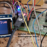
Fig. 1: Prototype of Arduino Based Music Notes and Melody Generator
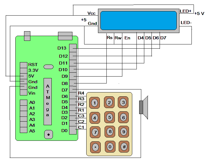
Circuit description:
As shown in circuit one 16×2 LCD, one 4×3 matrix keypad, and one 8Ω speaker is interfaced with arduino board.
• The Vcc pin (2) and Vss pin (1) of LCD are connected to +5 V and Gnd pins of arduino board respectively to provide it biasing.
• LED+ pin (15) and LED- pin (16) of LCD are also connected to +5 and Gnd pins respectively to turn ON LED backlight of LCD.
• Rs pin (4) and En pin (6) are connected with arduino digital pins 8 and 9 while Rw pin (5) is permanently connected to ground for write enable.
• Data pins D4 – D7 of LCD are connected with arduino digital pins 10 – 13
• 3 columns C1, C2, and C3 of matrix keypad are connected with 0,1 and 2 pins of arduino board while 4 rows R1, R2, R3, and R4 are connected with 3, 4, 5 and 6 pins.
• One 8Ω speaker is connected to pin 7 as shown in the circuit diagram.
Circuit operation:
• Initially, the message is displayed on LCD as “keypad tone generator”
• When any key is pressed, the key press is detected and arduino identifies which key is pressed
• Based on key number that is pressed, the particular frequency sound* (tone) is generated through speaker for 1 sec time
• The key number is displayed on LCD also the frequency of generated sound is displayed on LCD
• As shown in the figure the keypad is phone keypad (numeric) it includes * key and the # key. So when * key is pressed then it generates tone melody 1 and when # key is pressed it generates tone melody 2 that is displayed on LCD
*Note: the frequency of generated sound is chosen as to produce ‘sa’, ‘re’, ‘ga’, ‘ma’, ‘pa’, ‘dha’ and ‘ni’ all seven notes of music
The complete functionality of this project is due to the software program loaded into internal FLASH memory of arduino board microcontroller ATMega328. So let us see the program and its logic explanation.
Software program and logic:
The software program is written in arduino language. It is compiled using arduino IDE software tool and uploaded into internal FLASH memory of arduino board microcontroller. We all know arduino IDE has powerful library package that includes a complete set of functions for the particular peripheral device. In this program, we are using three libraries:
1) matrix keypad – to interface matrix keypad with arduino
2) liquid crystal – to interface LCD with arduino
3) tone generator – to generate different frequency sound
The matrix keypad library allows us to configure our matrix keypad as a number of rows-columns, key pattern etc everything. It detects key press, identifies which key is pressed and does many other functions. Liquid crystal library is as we know especially to interface different types of LCDs with arduino. It configures LCD, displays text, numeric data, clears LCD, sets cursor positions, etc. Tone generator is used to generate particular frequency sound from any digital pin of arduino.
You may also like:


Project Source Code
###
//Program to #include#include const byte ROWS = 4; // Four rows const byte COLS = 3; // Three columns int sound[10] = {1047,1109,1245,1319,1397,1480,1568,1661,1760,1865}; int sound_pin = 7; // Define the Keymap char keys[ROWS][COLS] = { {'1','2','3'}, {'4','5','6'}, {'7','8','9'}, {'#','0','*'} }; // Connect keypad ROW0, ROW1, ROW2 and ROW3 to these Arduino pins. byte rowPins[ROWS] = { 3, 4, 5, 6 }; // Connect keypad COL0, COL1 and COL2 to these Arduino pins. byte colPins[COLS] = { 0, 1, 2 }; // Create the Keypad Keypad kpd = Keypad( makeKeymap(keys), rowPins, colPins, ROWS, COLS ); LiquidCrystal lcd(8, 9, 10, 11, 12, 13); #define ledpin 13 void setup() { pinMode(ledpin,OUTPUT); digitalWrite(ledpin, HIGH); lcd.begin(16, 2); lcd.clear(); lcd.print(" keypad tone"); lcd.setCursor(4,1); lcd.print("generator"); } void loop() { int i; char key = kpd.getKey(); if(key) // Check for a valid key. { switch (key) { case '*': lcd.clear(); lcd.print("playing melody 1"); for(i=0;i<10;i++) tone(sound_pin,sound[i],500); break; case '#': lcd.clear(); lcd.print("playing melody 2"); for(i=0;i<10;i++) tone(sound_pin,sound[10-i],500); break; default: lcd.clear(); lcd.print("key:"); lcd.print(key); lcd.setCursor(0,1); lcd.print("sound "); lcd.print(sound[key-48]); lcd.print(" Hz"); tone(sound_pin,sound[key-48],1000); break; } } } ###
Circuit Diagrams
Project Video
Filed Under: Arduino, Electronic Projects
Filed Under: Arduino, Electronic Projects

Questions related to this article?
👉Ask and discuss on Electro-Tech-Online.com and EDAboard.com forums.
Tell Us What You Think!!
You must be logged in to post a comment.