In the previous tutorial, boolean arithmetic was introduced. It was shown that how binary numbers can be added, subtracted, multiplied and divided. In this tutorial, now logic operations on binary numbers will be discussed. The logic operations are not only the way to implement arithmetic operations (by means of combinational circuits), they form the building blocks of the digital circuits. A digital circuit is built by logic gates where the logic gates perform one or the other boolean logic operation.
The digital information is stored in a computing system in binary cells. A binary cell is a device that can have either a HIGH logic or LOW logic state and so can store one bit of information. In a positive logic system, voltage between 2 V to 5V as input signal level (at a TTL Gate) and 2.7 V to 5 V as output signal level (from a TTL Gate) is considered as HIGH logic and any voltage between 0 V to 0.8 V as input signal level (at a TTL Gate) and 0V to 0.5 V as output signal level (from a TTL Gate) is considered as LOW logic. In a negative logic system, it is vice-versa. The voltage levels between HIGH and LOW logic levels are called transition levels and the digital circuits (logic gates) are not responsive to them.
A group of binary cells is called register. The registers are used to store digital information on a computing system (processor or microcontroller). There can be 8-bit (8 binary cells in single register), 16-bit (16 binary cells in single register), 32-bit (32 binary cells in single register) or 64-bit (64 binary cells in a single register) registers in a 8-bit, 16-bit, 32-bit or 64-bit computing system respectively. The digital circuits fetch binary information stored in registers and operate on it according to their digital circuitry built by logic gates, then again store the result back in other registers.
The binary number stored in a binary cell or register can be treated as binary or boolean variable. The operations on these boolean variables (formed by digits 0 and 1) follow a set of mathematical rules which is referred as boolean algebra. The operations on a set of boolean variables by a digital circuitry can be expressed mathematically as a boolean function. So, a boolean function is formed by binary constants, binary variables and logic operators. The basic logic operations in boolean algebra are AND, OR and NOT operations. The AND, OR and NOT operations are performed by AND, OR and NOT logic gates respectively in a digital circuitry.

Fig. 1: Representational Image of Boolean Logic Operations
AND Operation –
The logical AND operation is equivalent to multiplication of bits. If two bits are multiplied then if both bits are 1 then only the result is 1, otherwise if either bit is 0 or both bits are 0, the result is 0. In boolean algebra, the AND operation is represented by dot or absence of operator. Suppose, there are two boolean variables A and B, then logical AND between A and B is represented by A.B or AB. If the result of this AND operation is stored in a variable Y, then it will be written as A.B = Y or AB = Y. This will be read as ‘A AND B is equal to Y’. All the possible results of AND operation between two single-bit variables A and B are shown in the following truth table –

Fig. 2: Truth Table of AND Operation
OR Operation –
The logical OR operation is equivalent to addition of bits. If two bits are added then if both bits are 0 then only the result is 0, otherwise if either bit is 1 or both bits are 1, the result is 1. In boolean algebra, the OR operation is represented by plus operator. Suppose, there are two boolean variables A and B, then logical OR between A and B is represented by A + B. If the result of this OR operation is stored in a variable Y, then it will be written as A + B = Y. This will be read as ‘A OR B is equal to Y’. All the possible results of OR operation between two single-bit variables A and B are shown in the following truth table –
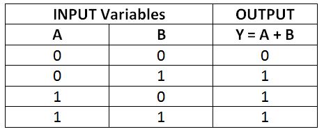
Fig. 3: Truth Table of OR Operation
NOT Operation –
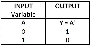
The NOT operation applies to a single operand. It is equivalent to 1’s compliment of a binary variable. If a single bit boolean variable has logic state 0, its NOT operation will result in 1 and vice-versa. It is represented by prime or an overbar. Suppose, if a boolean variable A is taken operand, the NOT operation on it will be represented by A’ or Ā. If it is stored in a variable Y, it will be written as A’ = Y or Ā = Y. It will be read as ‘not A is equal to Y’. Since the not operator inverts the bits in the operand variable, it is also called logical inverter. All the possible results of NOT operation on a single-bit variable A are shown in the following truth table – NOT Operation –
Fig. 4: Truth Table of NOT Operation
Boolean Algebra –
The logical operations on boolean variables follow a set of rules which is referred as boolean algebra. By the rules of boolean algebra, the boolean variables combined with logic operators (AND, OR and NOT) can be expressed as boolean functions. The AND, OR and NOT are the basic operators in boolean algebra. Every boolean algebraic expression (a boolean function) is always expressed in the form of AND, OR and NOT operations on boolean variables. There can be one, two, three or any number of boolean variables in a boolean function or boolean algebraic expression. Boolean Algebra –
Practically, each boolean variable represents a bit or serial combination of bits in a computing system. By implementing, a series of logic operations on a set of boolean variables (each variable fetched from a binary cell or register) over a data path, digital circuitry perform computation (binary arithmetic and so binary algebra) on the input data (represented by boolean variables).
Boolean Addition –
The Boolean addition on individual bits is performed by OR operation. It is governed by the following rules –
0 + 0 = 0
0 + 1 = 1
1 + 0 = 1
1 + 1 = 1
It can be seen that boolean addition on two bits is same as logical OR operation on them.
Boolean Multiplication –
The Boolean multiplication on individual bits is performed by AND operation. It is governed by the following rules –
0 · 0 = 0
0 · 1 = 0
1 · 0 = 0
1 · 1 = 1
It can be seen that boolean multiplication on two bits is same as logical AND operation on them.
Boolean Compliment –
The compliment of a boolean variable is performed by NOT operation. It is governed by the following rules –
0′ = 1
1′ = 0.
It can be seen that boolean compliment (1’s compliment) on a bit is same as logical NOT operation on it.
Now, it must be clear that by implementing logic operations (OR, AND, NOT), arithmetic operations on binary numbers (and so digital data) can be performed. In the next tutorial, learn about various logic gates. The logic gates perform the basic logic operations (AND, OR, NOT) and other logic operations (derived from AND, OR and NOT). The logic gates are the building blocks of a digital circuit. Any boolean algebraic expression or boolean function can be expressed and minimized to basic logic operations between boolean variables (data fetched over data paths) which then can be practically fabricated on a digital circuit as interconnection between logic gates.
You may also like:
Filed Under: Digital Electronics, Tutorials






Questions related to this article?
👉Ask and discuss on Electro-Tech-Online.com and EDAboard.com forums.
Tell Us What You Think!!
You must be logged in to post a comment.