
In the previous tutorial, all the possible boolean functions between two variables were discussed. In the tutorial – Boolean Algebra, various theorems and postulates were stated which are useful in simplifying a boolean expression or function. However, the simplification of a boolean expression using theorems and postulates is quite cumbersome and prone to errors. Therefore, for simplification of boolean expressions, some map methods were devised. The most commonly used map method is Karnaugh Map or K-Map.
Gate Level Implementation – DE Part 8

In the previous tutorial, gate level minimization of boolean functions was discussed. A boolean function must be expressed in standard form as either sum of products (SoP) or product of sums (PoS). Once a boolean function in case is minimized to SoP or PoS form, it can be easily fabricated as two-level implementation of AND and OR gates. A two-level implementation is preferred so that there is minimum delay in signal propagation through logic gates from input to output of the digital circuit.
Arithmetic Circuits – DE Part 10

The previous tutorials laid the foundation for logic synthesis and design of digital circuits. The digital circuits in general always have application as computing devices either as processor, controller or application specific ICs. As a computing device, the digital circuitry of a processor, controller or ASIC must be essentially able to perform arithmetic operations. The implementation of arithmetic operations by digital circuitry is further used to build up complex computing logics and mathematical functions.
Logic gate implementation of arithmetic circuits – DE Part 11
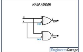
In the previous tutorial, the basic combinational arithmetic circuits like half adder, full adder, half subtractor and full subtractor were discussed in details. Now, in this tutorial, the truth table and derivation of the boolean expressions for all those circuits will be considered. With the derived boolean expressions, all those circuits will be practically designed using digital ICs.
Sequential Logic Circuits – DE Part 17

In the previous tutorials, all the circuits designed were combinational circuits. In combinational circuits, the binary output is dependant only on the current state of the inputs. So, actually, the combinational circuits have a static operation. They can have input from a fixed set of values for which the output is known to outcome in a defined range at any instant of time.
Flip Flops – DE Part 18
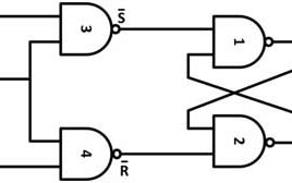
In the previous tutorial, basics of sequential logic circuits were discussed. It was mentioned that sequential circuits can be of two types – synchronous and asynchronous. The sequential circuits are different from combinational circuits in the way that they have memory elements for feedback of previous input states. The asynchronous circuits use latches as the memory elements. The latches cannot be used as memory elements in synchronous circuits as the synchronous circuits require transition sensitive devices to operate against clock signals.
Registers – DE Part 19
In the previous tutorial, the concept and construction of flip flops was discussed. The flip flops are essential building block of any synchronous or clocked sequential circuit. Without flip flops, a clocked sequential circuit is reduced to a combinational circuitry. Even flip flops alone are considered sequential circuits. There are two types of sequential circuits that are solely constructed from the flip flops – Registers and Counters.
Counters – DE Part 20
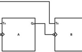
In the previous tutorial, different types of registers were discussed. The registers and counters are two types of sequential circuits that are solely build from flip flops. The counters are those registers that go through predetermined sequence of states on the application of input pulses. The input pulses can be coming from a master clock or some external source. They may apply to the counter either at regular interval or randomly. There are two types of counters – Asynchronous counter (also known as ripple counter) and Synchronous counter.
Memory Devices for Digital Systems – DE Part 21

In the previous tutorials, it was learnt that sequential circuits require memory elements to retain previous states of a digital system. The flip-flops and registers were then introduced as building blocks of memory in a sequential circuit. The registers are enough to store runtime data in small microcontrollers and ASICs. The complex computing systems require digital memory to not only store runtime information (as stored by registers in a microcontroller) but to store programs and data permanently within the digital system. So, they require dedicated memory either internal or external.
Building Code Convertors Using SN-7400 Series ICs – DE Part 12
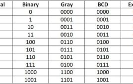
In the first tutorial of this series – Introduction to Digital Electronics, it was mentioned that there are different code systems that are used to represent digital information as binary numbers. Each code system has different binary numbers assigned to same symbols and characters. The different digital systems may be using different code systems. In such case, there must remain some code conversion circuit to make the interconnected digital systems compatible.
Introduction to DE- Representing everything into numbers – DE Part 1

Humans collect information about the nature and organize it as ‘science’. The very foundation of science i.e. organized knowledge about understanding of nature and natural phenomena, is based on language and mathematics. Any branch of science involves identification of entities, their attributes, associated events and mathematical analysis of those attributes and events. Such structural analysis of nature and natural phenomena begins with quantification of physical things and their properties, i.e. representation by name and properties of things and events as discrete information (words) and measurement of every possible property in numbers. This is the basic nature and method by which the humans explore the world.
Binary arithmetic operations – playing with the numbers
In the previous tutorial, it was discussed that how any information can be represented by numbers and a set of numbers (code systems)can be used to store and manipulate information. A lot of real-world information is mathematical in nature like count of things, measurements of quantities etc. Such information may further have mathematical relationships. In order for a computer (digital circuit) to perform computing (mathematical operations) on such information, it must be first able to perform arithmetic operations. The arithmetic operations are the basic mathematical operations. Only by performing arithmetic operations, other algebraic operations can be performed on numerical data.
Boolean Logic Operations – Logic to start building digital circuits – DE Part 3
In the previous tutorial, boolean arithmetic was introduced. It was shown that how binary numbers can be added, subtracted, multiplied and divided. In this tutorial, now logic operations on binary numbers will be discussed. The logic operations are not only the way to implement arithmetic operations (by means of combinational circuits), they form the building blocks of the digital circuits. A digital circuit is built by logic gates where the logic gates perform one or the other boolean logic operation.
Logic Gates – Building Blocks of Digital Circuits – DE Part 4
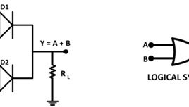
In the previous tutorial, it was discussed how arithmetic operations on binary numbers can be implemented by the means of boolean logic operations. In a digital circuit, the logic operations are executed by logic gates. A Logic gate is an electronic circuit which makes logical decisions. The AND, OR and NOT are the basic logic gates.
Boolean Algebra – Boolean Expressions and the Digital Circuits – DE Part 5
In the previous tutorial, various logic gates and their construction was discussed. In the tutorial – Boolean Logic Operations, it was discussed that how by performing logical operations on binary data, arithmetic operations can be executed. In a digital circuit, many logic gates are interconnected along with registers and memory elements to carry out a complex computation task. Any computational problem can be expressed as a boolean function or boolean expression.
All Boolean Logical Operations – DE Part 6
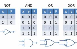
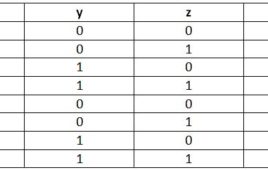
In the previous tutorial, various boolean postulates and theorems were discussed. These theorems and postulates are useful in deducing a boolean expression. It was also discussed that for n number of variables, there can be maximum 2^2n boolean functions. So, there can be maximum 16 (2^4) boolean functions between two boolean variables. A boolean variable represents a singular binary data source in digital electronics i.e. a single bit or serial stream of bits. So, there can be maximum 16 logical functions in digital circuits. Let us learn about all the logical operations.
Introduction to VHDL & Verilog – DE Part 9

In the previous tutorials, boolean functions, boolean expressions, minimization of boolean expressions and implementation of a boolean function into logic gate diagram was discussed. It is possible to minimize a boolean function with less number of boolean variables and implement a logic gate diagram for it manually. But as the number of variables in a boolean function increases, not only its minimization becomes complex, designing a logic gate implementation for it also becomes cumbersome. In such case, computer based design tools are the ultimate resort.
More Combinational Circuits – Multiplexers, Demultiplexers, Encoders and Decoders – DE Part 14
In digital systems, any information is represented by binary codes. There are many binary code systems as mentioned in the first tutorial of this series. A binary code of n bits can represent 2n discrete symbols or elements of coded information. The digital circuits that perform encoding of digital information are called encoders while digital circuits that decode the coded digital information are called decoders. An encoder with enable pins is called multiplexer while a decoder with enable pins is called demultiplexer.
RAM and ROM Memories – DE Part 22

In the previous tutorial, it was mentioned that primary memory can be of two types – Random Access Memory and Read Only Memory. These memories are essential part of any processor or controller based system. In this tutorial, these memories will be discussed in detail.
Building Multiplexer and Demultiplexer using SN-7400 Series ICs – DE Part 16
In the previous tutorial, encoder and decoder circuits were built using SN-7400 series logic gate ICs. The multiplexer and demultiplexer are also combinational circuits similar to encoder and decoder. A multiplexer is a circuit that accepts many inputs and channelize digital data to only one output. The combinational circuit of a multiplexer is similar to encoder with only difference that the multiplexer has select inputs that determine from which input the data should be channelized to the output. Like encoder, a multiplexer circuit can be built using AND, NOT and OR gates.