Cell phone operated Robot is a Robot whose movement can be controlled by pressing the number of cell phone. The robot can move forward, backward, right or left which depends on the numbers you are pressing. The property of Robot to operate by the cell phone helps you to operate the robot from some distance The Cell Phone controlled Robot uses DTMF (Dual tone-multi frequency) module. It is capable of receiving a set of command (instructions) in the form of DTMF (Dual tone multiple frequency) tones and performs the necessary actions. The robot is controlled by making call to the mobile connected to the robot. The robot performs various operations like moving forward, backward etc. if any key is pressed in the course of the call, by hearing at the other end of the call (i.e. at the mobile connected to the robot ). Each key corresponds to a particular frequency which is decoded by the DTMF decoder & processed by logic circuit by giving each key a particular operation like moving forward, backward, right, left etc. The benefit is that we can operate the robot by using any mobile with the working range as large as the coverage area of the service provider.
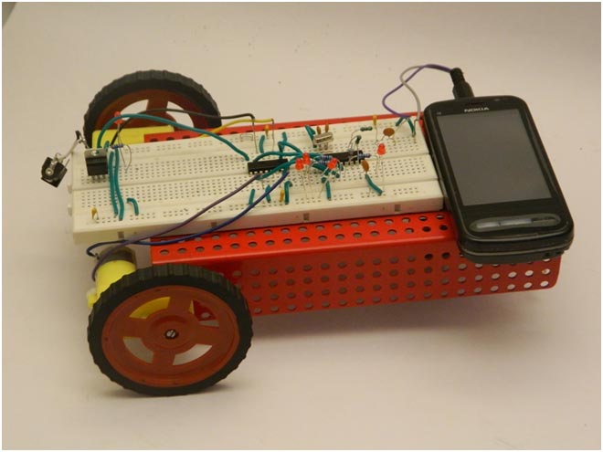
Fig. 1: Prototype of DTMF based Mobile Operated Robotic Car
Block Diagram
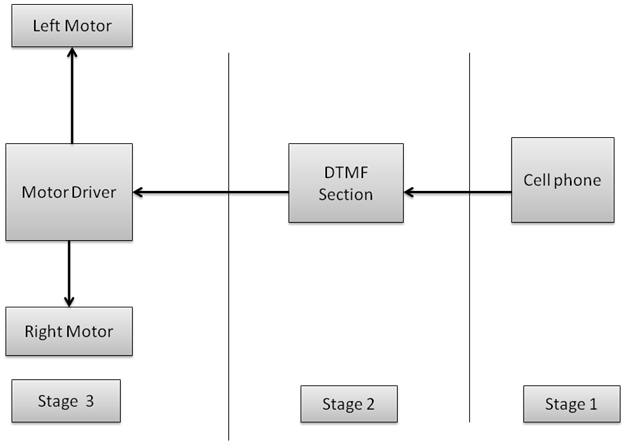
Fig. 2: Block Diagram of DTMF based Mobile operated Robottic Car
Cell phone controlled robot are used to operate the robot by using cell phone. By connecting cell phone to the circuit the cell phone can controlled robot through the by the keypad of cell phone.
Stage 1
Cell phone
Cell phone are used to give the instruction to the robot by pressing the keypad of the cell phone. The output of the cell phone controlled robot are dual tone frequency which is received by the DTMF receiver.
Stage 2
DTMF Receiver Section
DTMF receiver section are used to receive the dual tone coming from the cell phone. It is received by the DTMF and decoded by the same DTMF IC and given to the further circuit.
DTMF IC
To receive the dual tone frequency from the cell phone and to convert it into usable signal we have use HT9370 IC Here we are given explanation of the HT9170 IC ,Both IC are compatible with each other.
HT9170 IC
HT9170 is the series of Dual Tone Multi Frequency (DTMF) receivers. They employ digital counting techniques to detect and decode the 16 DTMF tones into 4 bit output code.HT9170 series receivers do not require any external filters as they use highly accurate switched capacitor filters for filtering low and high frequency signals from the DTMF tones. They also support power down (PWDN) and inhibit (INH) modes. PWDN mode is used to power off the crystal, while INH mode to inhibit the A, B, C & D DTMF tones. The clock is provided by a 3.58 MHz crystal.
In simple terms, HT9170 IC detects and decodes the 16 DTMF tones into 4 bit output. In case the tones are not detected, the four output bits remain low. The DV pin goes high on detection of a valid tone.
Pin Diagram:
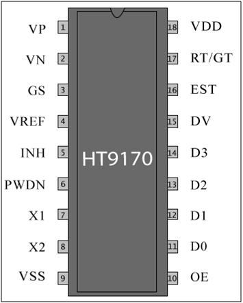
Fig. 3: Pin Diagram of HT9170 DTMF Receiver IC
Pin Description:
|
Pin No |
Function |
Name |
|
1 |
Operational amplifier non-inverting input |
VP |
|
2 |
Operational amplifier inverting input |
VN |
|
3 |
Operational amplifier output terminal |
GS |
|
4 |
Reference voltage output terminal |
VREF |
|
5 |
Active high. It inhibits the detection of tones corresponding to A, B, C and D. It is internally pulled down. |
INH |
|
6 |
Active high. It leads the chip to power down mode and inhibits the oscillator. It is internally pulled down |
PWDN |
|
7 |
Connection for standard 3.579545 MHz crystal |
X1 |
|
8 |
X2 |
|
|
9 |
Ground (0V) |
VSS |
|
10 |
Active high; Enables output D0-D3 |
OE |
|
11 |
Output terminals |
D0 |
|
12 |
D1 |
|
|
13 |
D2 |
|
|
14 |
D3 |
|
|
15 |
Data valid. It goes high on reception of valid DTMF signal; otherwise remains low |
DV |
|
16 |
Early steering output |
EST |
|
17 |
Tone acquisition time and release time can be set by using external resistor and capacitor |
RT/GT |
|
18 |
Supply voltage; 5V (2.5V-5.5V) |
VDD |
Motor Driving Stage
Stage 3
Motor Driving Stage
In this stage the motor driver L293D IC is used for to drive the motor. As the signal comes from the inverter IC it drives the motor according to signals comes.
L293D IC
L293D is a dual H-bridge motor driver integrated circuit (IC). Motor drivers act as current amplifiers since they take a low-current control signal and provide a higher-current signal. This higher current signal is used to drive the motors.
L293D contains two inbuilt H-bridge driver circuits. In its common mode of operation, two DC motors can be driven simultaneously, both in forward and reverse direction. The motor operations of two motors can be controlled by input logic at pins 2 & 7 and 10 & 15. Input logic 00 or 11 will stop the corresponding motor. Logic 01 and 10 will rotate it in clockwise and anticlockwise directions, respectively.
Enable pins 1 and 9 (corresponding to the two motors) must be high for motors to start operating. When an enable input is high, the associated driver gets enabled. As a result, the outputs become active and work in phase with their inputs. Similarly, when the enable input is low, that driver is disabled, and their outputs are off and in the high-impedance state.
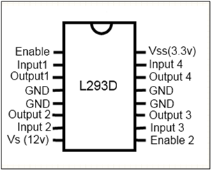
Fig. 4: Pin Diagram of L293D Motor Driver IC
Truth table for robot Movement
|
Sr.No |
IN1 |
IN2 |
IN3 |
IN4 |
Movement of robot |
|
1 |
1 |
0 |
0 |
1 |
Forward |
|
2 |
1 |
1 |
1 |
1 |
Stop |
|
3 |
1 |
0 |
1 |
0 |
Left |
|
4 |
0 |
1 |
0 |
1 |
Right |
The signal logic will be changed as per the condition.
Steps to Build the Cell Phone Controlled Robot
Accessories Required to make cell phone controlled robot
|
Sr.No. |
Component Name |
Quantity |
| 1. | Double AA batteries cell holder | 1 |
| 2. | Chassis ( Robotic Platform) | 1 |
| 3 | Breadboard | 1 |
| 4 | Nipper | 1 |
| 5. | Stripper | 1 |
| 6. | One core wire | As per the use |
| 7. | Nose pliers | 1 |
| 8 | Screw driver | 1 |
Mechanical Assembly of robotic chassis
Step 1:
Take a robotic chassis.
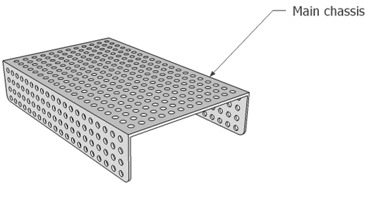
Fig. 5: Representational Image of Main Chassis of Robot
Step 2:
Take the BO motor as shown in the diagram.
Step 3:
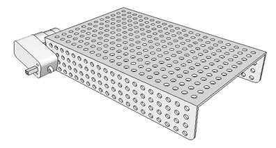
Fig. 6: Image showing motor attachment to robot’s chassis
Take a M2.5 (25) screw to fit the BO motor on the chassis. Fit the motor in upward direction as shown in the figure. Here the last hole of the chassis are used to fit the motor.
Note
Here kept the motor screw M2.5 (25) in the separate polyethene and also don’t mix it with other screw.
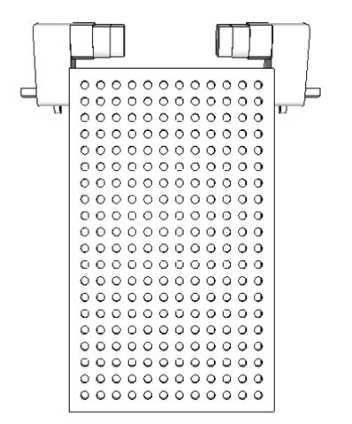
Fig. 7: Image showing motor attachment on both sides of robot’s chassis
Step 4
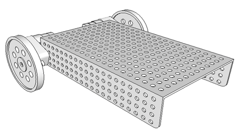
Fig. 8: Image showing attachment of wheels to motors on robot
Fit the both wheel on the both motor shaft as shown in figure. Fix the motor with self tapping red wheel screw.
Step 5
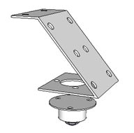
Fig. 9: Representational Image of Caster Wheel and Strip for Robot
Take the caster wheel and caster wheel strip as shown in the diagram.
Step 6
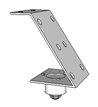
Fig. 10: Image showing attachment of Caster Wheel to Strip for Robot
Inset three M3 -10 screw into the caster wheel. Now fit the caster wheel into the caster wheel strip in the outward direction as shown in the figure.
Step 7
Now fit the caster wheel strip on the middle position of the chassis as shown in the diagram by using two M3-10 screw.
Now your robotic platform is ready to be used.
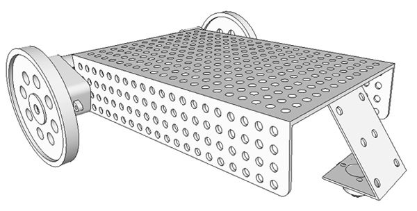
Fig. 11: Image showing attachment of Caster Wheel strip to Chassis of Robot
Breadboard Connection
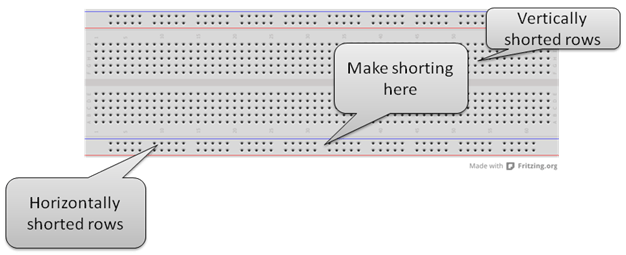
Fig. 12: Image showing rows and columns on a Breadboard
· Give positive +5 volt supply in first row.
· Connect the GND in the second row of the breadboard.
· Connect + 5 volt upper row with the below row to make below line +5 volt .
· Connect the upper gnd line with the lower gnd line to make the below row gnd line.
· Short the below middle rows as connect the +5 volt to +5volt line and gnd line with the gnd line.
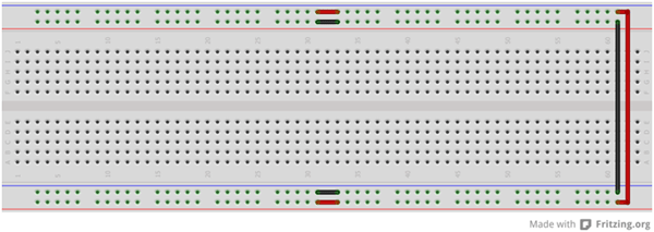
Fig. 13: Typical image of Breadboard
Construction of cell phone controlled robot on breadboard
· Power Supply
· Motor Driver
· DTMF module
Designing Power Supply Section
Power Supply
General Description
Power supply is used for to give power to the whole circuit assembly. The below component are used for to make power supply section.
Component list for power supply
|
Sr.No. |
Component Name |
Component list |
| 1 | DC jack | 1 |
| 2 | 7805 voltage regulator IC | 1 |
| 3 | 3 mm Led | 1 |
| 4 | Resistor (220 ? ) (Red, Red, Black, Black ) | 1 |
Explanation of component
Make the below connection for power supply as given in below image.
DC jack
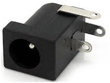
Fig. 14: Typical Image of DC Jack
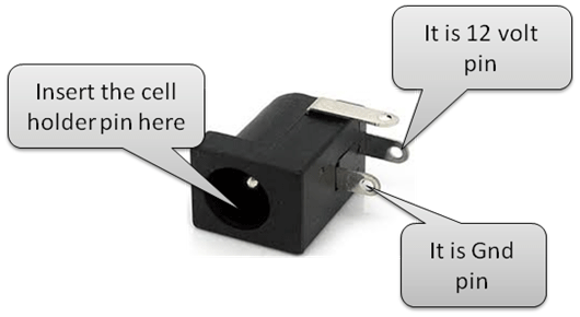
Fig. 15: Pin Diagram of DC Jack
7805 Connection pin diagram
|
Sr .No |
7805 Pin No |
7805 Pin name |
|
1 |
Pin 1 |
+12 volt (Given by battery) |
|
2 |
Pin 2 |
Gnd |
|
3 |
Pin3 |
+ 5 (output to give whole circuit ) |
By referring below images you can make the power supply circuit
1. Breadboard Image
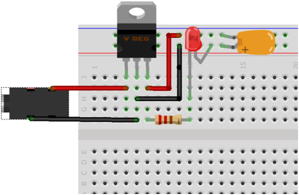
Fig. 16: Representational Image of Power Supply Circuit on Breadboard
2. Schematic Diagram for power supply
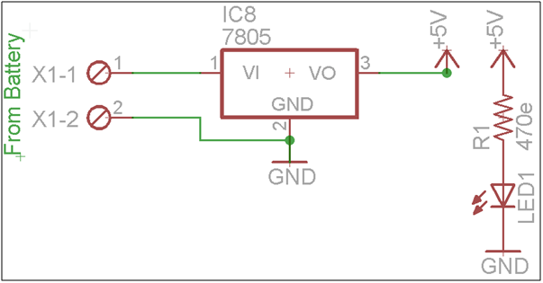
Fig. 17: Circuit Diagram of Power Supply for Robot
Testing of power Supply Section
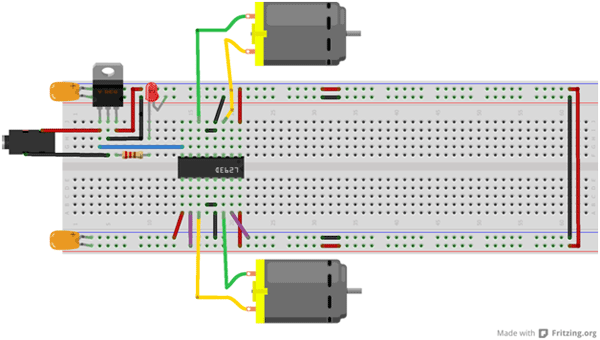
Fig. 18: Representational Image of Motor Driver Circuit on Breadboard
If the led will be glow it means the power supply circuit connection is correct. and now you can able to give power to whole the assembly.
Designing Motor Driver Section
Motor driver section
General Description
Now you have make a motor driver section which is used for to drive the motor. Here to drive the motor you have use L293D IC.
Component List for Motor Driver Section
|
Sr No |
Component Name |
| 1. | L29D3 IC Section |
| 2. | One core wire |
Designing of motor driver section
By referring below images and table you can make and test the motor driver section.
L293D pin connection
|
Sr.No |
L293 D pin |
Supply voltage |
| 1 | Pin no 1 | +5 volt |
| 2 | Pin no 9 | +5 volt |
| 3 | Pin no 16 | +5 volt |
| 4 | Pin no 8 | +12 volt |
| 5 | Pin no 4 & 5 | Gnd |
| 6 | Pin no 12 & 13 | Gnd |
Connection of Motor with L293D IC
|
Sr. No. |
Output pins |
Motor Wire |
| 1 | o/p1 | First wire of first motor |
| 2 | o/p2 | Second wire of first motor |
| 3 | o/p3 | First wire of second motor |
| 4 | o/p4 | Second wire of second motor |
Breadboard Image

Fig. 19: Representational Image of Motor Driver Circuit on Breadboard
Schematic image of motor driver section
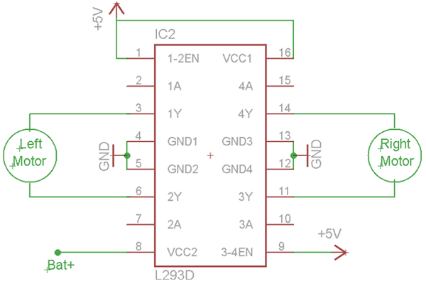
Fig. 20: Circuit Diagram of L293D IC based Motor Driver
Give the below supply at input terminal of L293d IC to test the motor
|
Sr.No. |
Pins Name |
Given supply |
|
1 |
In1 |
+5 |
|
2 |
In2 |
Gnd |
|
3 |
In3 |
+5 |
|
4 |
In4 |
Gnd |
Note
· Short 4 (gnd) and 5 (gnd) pin with the jumper. Jumper can be taken from the wire.
· In the same way also short pin no 12 (gnd) and 13(gnd) of the l293D IC.
Testing of motor driver section
Step 1
Connect one wire of first motor with the o/p1 pin of L293D IC. And second one is with second o/p2 of L293D IC.
The motor should be rotate in clockwise direction from your front side. If the motor rotate in anticlockwise direction than make it in clockwise direction by exchanging it’s wire with L293D o/p pins.
Step 2
Connect one wire of second motor with the o/p3 pin of L293D IC. And second one with second o/p4 of L293D IC.
Now the motor should be rotate in anticlockwise direction from your front side. If the motor rotate in clockwise direction than make it in anticlockwise direction by exchanging it’s wire with L293D o/p pins.
DTMF Module
Now the chassis should be moves in the forward direction.
DTMF Module
General Description
DTMF module are used to receive the signal coming from the cell phone and control the robot through the output signal coming from the DTMF IC.
DTMF Module
To make the DTMF module below component are required .
Component required to make logic circuit is as given below table.
|
Sr.No. |
Component Name |
Quantity |
| 1. | HT9370 IC | 1 |
| 2. | 3.57 Hz Crystal | 1 |
| 3. | Led ( 5mm ) | 4 |
| 4. | 10k ? R9 ( Brown, Black ,Black, Red) | 4 |
| 5. | 100K ? R8 (Brown, Black, Black, Orange) | 2 |
| 6. | Capacitor C1 & C2 (33pF) Ceramic Capacitor | 2 |
| 7. | Capacitor C4 ( 104) Ceramic Capacitor | 1 |
| 8. | Capacitor C5(104) ceramic Capacitor | 1 |
| 8. | 330 k (Orange, Orange, Black, Orange) | 1 |
| 9. | Audio Jack | 1 |
Component Explanation
Audio Jack

Fig. 21: Typical Image of Audio Jack
Audio Jack are used for to connect the cell phone with the DTMF circuit.
Open the audio jack and connect the longest terminal ( GND ) with the ten core wire and left hand side smallest terminal ( input terminal ) with another ten core wire.
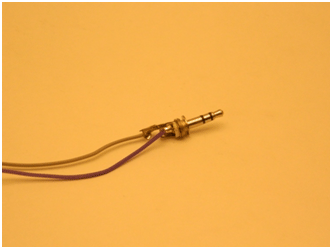
Fig. 22: Image showing internal wiring of Audio Jack
Connect the input pin with the one terminal of the capacitor and another with the GND terminal.
Connection of DTMF Module IC section
|
Sr.No |
Pin no |
Component Connection |
| 1 | 1 | Short with pin no 4 |
| 2 | 2 | 100 k resister and 104 capacitor |
| 3 | 3 | 100 k resister with pin no 2 |
| 4 | 5 | Short with pin no 9 |
| 5 | 6 | Short with pin no 9 |
| 6 | 7 & 8 | 3.57 MHz crystal |
| 7 | 10 | + 5 volt |
| 8 | 11,12,13,14 | 10k Resister with the positive terminal of led |
| 9 | 15 | Open |
| 10 | 16 | 330 k Resister |
| 11 | 17 | 104 capacitor |
| 12 | 18 | +5 volt |
Make also below connection
· Short the pin no 1 and 4 with the each other & also short the pin no 5 and 9 ,6 also.
· Connect the one terminal of 100 k resister with pin no 2 and another terminal with the one terminal of 104 capacitor and another terminal with the audion jack input.
· Connect the one terminal of the 100k to the pin no 3 and another terminal with the pin no 2.
· Connect the 3.57 MHz crystal with the pin no 7 & 8 and also connect one terminal of two 33pf capacitor with the crystal and another terminal with the gnd.
· Give the + 5 volt to the pin no 10 of the IC.
· Connect 11,12,13,14 pin with the one terminal of the 1k resister and another terminal with the positive terminal of the led and it’s negative terminal with the GND.
· Pin no 15 remains open.
· Pin no 16 with the one terminal of 330 k resister and it’s another terminal with the pin no 17.
· Connect pin no 17 with the one terminal of 104 capacitor and it’s another terminal pin with +5 volt.
· Give +5 volt to the pin no 18.
· Connect the input wire of the audio jack with the 104 capacitor and another GND with the GND pin on the breadboard.s
1. Breadboard image of DTMF Module
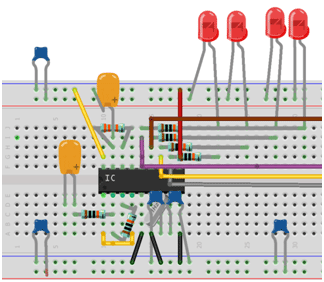
Fig. 23: Representational Image of DTMF Decoder Circuit on Breadboard
2. Schematic layout of DTMF Module section
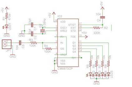
Fig. 24: Circuit Diagram of CM8870CP IC based DTMF receiver
Troubleshooting of the circuit
· Check the continuity of the whole circuit by placing Multimeter at the continuity mode.
· Also check the voltage at the different circuit points by using Multimeter. Also check the voltage at different pins of the IC.
· Connect the .1 µf capacitor in between the +5 and Gnd pin at the any random place of the breadboard.
· You can check the crystal frequency on the CRO. It should be comes approx 3.57 MHz .
· You can also check the audio signal waveform coming from the cell phone on the CRO. See the below image coming from the audio signal coming from the cell phone.
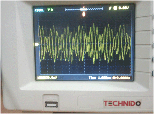
Fig. 25: Image of audio singnals from cell phone displayed on a CRO
Circuit Diagram & Complete Assembly
Fully connected circuit for cell phone controlled robot
Breadboard Image
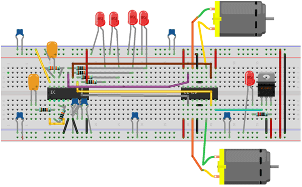
Fig. 26: Representational image of complete control ciircuitry for Robot on Breadboard
Schematic Image
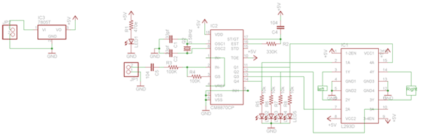
Fig. 27: Circuit Diagram of Mobile Operated Microcontroller-Less Robot
Connection of Motor with L293D IC
|
Sr. No. |
Output pins |
Motor Wire |
| 1 | o/p1 | First wire of first motor |
| 2 | o/p2 | Second wire of first motor |
| 3 | o/p3 | First wire of second motor |
| 4 | o/p4 | Second wire of second motor |
Connection of the DTMF module output with the L293D IC
Here Q1,Q2,Q3,Q4 are represents the Output of the DTMF module.
| Sr.No |
DTMF output |
L293D Output |
|
1 |
Q1 |
IN1 |
|
2 |
Q2 |
IN2 |
|
3 |
Q3 |
IN3 |
|
4 |
Q4 |
IN4 |
Movement of robotic platform
· Movement of the robotic platform depends on the as the motor connection with the L293D IC.
· Insert the audio jack with the cell phone and check the headphone indication on the screen of the mobile.
· Open the keypad window and send any key like 1,2,3.4 etc.
· Press any key from the cell phone like 1,2,3,4 and observe the robotic movement as per the key pressed.
Complete Assembly of cell phone controlled robot
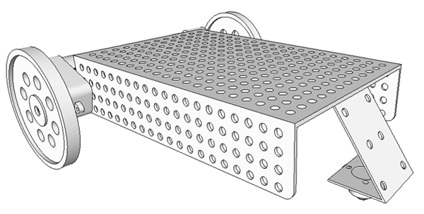
Fig. 28: Representational Image of complete assembly of mobile operated robot
· Also fit the breadboard on the robotic platform.
· Also take a battery cell holder and put it on the robotic platform.
· You can give supply to the robotic platform by the battery cell holder or by using 12 volt adaptor.

Fig. 29: Prototype of Mobile operated Robotic Car
You may also like:
Filed Under: Electronic Projects, Robotics






Questions related to this article?
👉Ask and discuss on Electro-Tech-Online.com and EDAboard.com forums.
Tell Us What You Think!!
You must be logged in to post a comment.