Engineers Garage

  • Electronics Projects and Tutorials
    • Electronic Projects
      • Arduino Projects
      • AVR
      • Raspberry pi
      • ESP8266
      • BeagleBone
      • 8051 Microcontroller
      • ARM
      • PIC Microcontroller
      • STM32
    • Tutorials
      • Audio Electronics
      • Battery Management
      • Brainwave
      • Electric Vehicles
      • EMI/EMC/RFI
      • Hardware Filters
      • IoT tutorials
      • Power Tutorials
      • Python
      • Sensors
      • USB
      • VHDL
    • Circuit Design
    • Project Videos
    • Components
  • Articles
    • Tech Articles
    • Insight
    • Invention Stories
    • How to
    • What Is
  • News
    • Electronic Product News
    • Business News
    • Company/Start-up News
    • DIY Reviews
    • Guest Post
  • Forums
    • EDABoard.com
    • Electro-Tech-Online
    • EG Forum Archive
  • DigiKey Store
    • Cables, Wires
    • Connectors, Interconnect
    • Discrete
    • Electromechanical
    • Embedded Computers
    • Enclosures, Hardware, Office
    • Integrated Circuits (ICs)
    • Isolators
    • LED/Optoelectronics
    • Passive
    • Power, Circuit Protection
    • Programmers
    • RF, Wireless
    • Semiconductors
    • Sensors, Transducers
    • Test Products
    • Tools
  • Learn
    • eBooks/Tech Tips
    • Design Guides
    • Learning Center
    • Tech Toolboxes
    • Webinars & Digital Events
  • Resources
    • Digital Issues
    • EE Training Days
    • LEAP Awards
    • Podcasts
    • Webinars / Digital Events
    • White Papers
    • Engineering Diversity & Inclusion
    • DesignFast
  • Guest Post Guidelines
  • Advertise
  • Subscribe

Countdown timer using 8051 microcontroller (AT89C51)

By Himanshu Choudhary August 3, 2010

A countdown timer is a down counter that counts from a specified time to 00:00. It is used in many devices such as washing machine, televisions, microwave ovens, etc. This countdown timer has three states: the running state where it counts down, the pause state where it displays the paused time and the reset state to set the countdown. The countdown is displayed on a set of four seven segment displays using the 8051 microcontroller (AT89C51). A buzzer sounds when the countdown gets over.


The countdown timer keeps the track of time the same way as a simple digital clock does. The control options are provided by means of tactile switches which are active low. This circuit uses five such switches for following operations:


Switch 1 (S1)   :           Reset               (to initiate the timer set option)
Switch 2 (S2)   :           Select              (to select the segment where value is to be changed)
Switch 3 (S3)   :           Increment        (to increase the value at selected segment)
Switch 4 (S4)   :           Start                (to start the timer with the set time)
Switch 5 (S5)   :           Pause               (to hold the time)
 
As soon as the Vcc supply is provided to the circuit, the timer goes in reset mode with 00:00 display state on seven segments. The segment to be set can then be selected in cyclic order each time S2 is pressed. After selecting the desired segment, its value can be changed by using S3. Once the digits and hence the time is set, S4 is pressed to start the countdown. The countdown can be held in between by using S5. If S5 is not pressed, the time runs until the 00:00 state is reached. At this instant, a buzzer connected to the microcontroller AT89C51 gets activated and produces sound to indicate that the countdown is over. To bring the timer back in reset mode, i.e., to set the countdown again, S1 needs to be pressed.
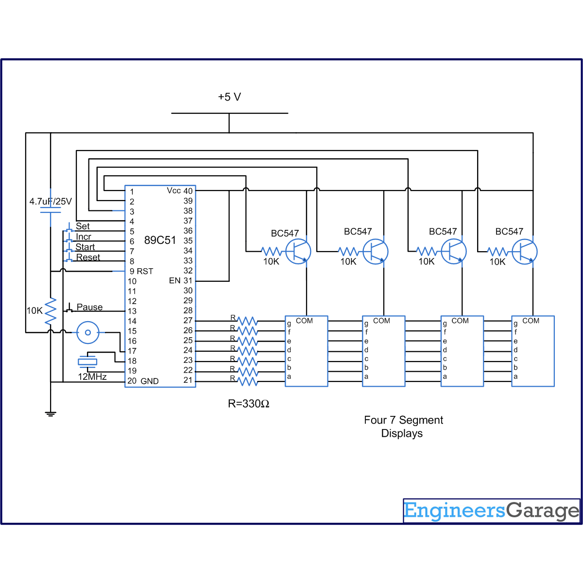
The seven segments are interfaced to port P2 of the microcontroller through its data pins (a – h). The enable pins are connected to pins 1-4 of port P1 (P1^0 – P1^3) of the microcontroller AT89C51. The switches S1-S5 and buzzer are connected as following:
S1         :           P1^7                                         S4         :           P1^6
S2         :           P1^4                                         S5         :           P3^3
S3         :           P1^5                                         Buzzer :           P3^7
The buzzer is connected to the output pin of microcontroller at the negative end and to Vcc at the positive end.


Project Source Code

###

// Program to make a timer similar to the timer in microwave. This countdown timer counts backwards from a set value and raise an alarm when the counting is complete.It also has a feature of pause.

#include<reg51.h>

sbit dig_ctrl_4=P1^0; //Declare the control pins for the seven segment
sbit dig_ctrl_3=P1^1;
sbit dig_ctrl_2=P1^2;
sbit dig_ctrl_1=P1^3;

sbit reset=P1^7;   //Reset pin to reset the timer.
sbit start=P1^6;  //Start pin to start the clock after the time is set.
sbit incr=P1^5;  //Increment pin to increase the digits for time setting.
sbit set=P1^4;  // Set pin to set the time.
sbit pause=P3^3; // Pause pin to pause the operation
sbit buzzer_pin=P3^7;

int sel_seg_to_incr=0;
int ret_seg_to_incre=0;
int recent_incr_seg;
int begin;
unsigned char dig_disp=0;
int min2=0;
int min1=0;
int sec2=0;
int sec1=0;
int p;
int avi=0;

char dig_val[10]={0x40,0xF9,0x24,0x30,0x19,0x12,0x02,0xF8,0x00,0x10};// Hex values corresponding to digits 0 to 9

void delay(int a)  // Function to provide a time delay of approx. one second using Timer 1.
{
int i;
  for(i=0;i<a;i++)
    {
  TL1=0xFD;
     TH1=0x4B;
     TR1=1;
   while(TF1==0);
   TR1=0;
   TF1=0;
}       
}

int setfn()  // Function to select minute and seconds digit to set value.
{     
while(set==0)
{

  switch(recent_incr_seg)
  {
   case 1:
   if(set==0)//select the min2 digit
   {
    dig_ctrl_4=1;
    dig_ctrl_3=0;
    dig_ctrl_2=0;
    dig_ctrl_1=0;
    recent_incr_seg=1;
    ret_seg_to_incre=1;
    P2=dig_val[min2];
    delay(15);
   }

   case 2:
   if(set==0)//select the min1 digit
   {
    dig_ctrl_4=0;
    dig_ctrl_3=1;
    dig_ctrl_2=0;
    dig_ctrl_1=0;
    recent_incr_seg=2;
    ret_seg_to_incre=2;
    P2=dig_val[min1];
    delay(15);
   }

   case 3:
   if(set==0)//select the sec 2 digit
   {
    dig_ctrl_4=0;
    dig_ctrl_3=0;
    dig_ctrl_2=1;
    dig_ctrl_1=0;
    recent_incr_seg=3;
    ret_seg_to_incre=3;
    P2=dig_val[sec2];
    delay(15);
   }

   case 4:
   if(set==0)//select the sec1 digit
   {
    recent_incr_seg=1;
    dig_ctrl_4=0;
    dig_ctrl_3=0;
    dig_ctrl_2=0;
    dig_ctrl_1=1;
    ret_seg_to_incre=4;
    P2=dig_val[sec1];
    delay(15);
    recent_incr_seg=1;
   }
  }
}
return(ret_seg_to_incre);
}

void increase(int a) //Function to set the minutes or seconds digit
{
while(incr==0)
{
  switch(a)
  {
   case 1: // Set the min2 digit.
   P2=dig_val[min2];
   delay(15);
   min2++;
   if(min2==6)
   min2=0;
   P2=dig_val[min2];
   delay(5);
   break;

   case 2: //Set the min1 digit.
   P2=dig_val[min1];
   delay(15);
   min1++;
   if(min1==10)
   min1=0;
   P2=dig_val[min1];
   delay(5);
   break;
 
   case 3:// Set the sec2 digit.
   P2=dig_val[sec2];
   delay(15);
   sec2++;
   if(sec2==6)
   sec2=0;
   P2=dig_val[sec2];
   delay(5);
   break;

   case 4://Set the sec1 digit.
   P2=dig_val[sec1];
   delay(15);
   sec1++;
   if(sec1==10)
   sec1=0;
   P2=dig_val[sec1];
   delay(5);
   break;
  }
}
}

void resetfn() // This function brings the clock to reset or set mode.
{

IE=0x84; // Disable Timer0 interrupt to stop the display of the clock
sel_seg_to_incr=1;
recent_incr_seg=1;
if(begin==0)
{
  dig_ctrl_4=1; //Enable the min2 digit and disable others
  dig_ctrl_3=0;
  dig_ctrl_2=0;
  dig_ctrl_1=0;
}
begin=0;
P2=dig_val[min2];
delay(5);
while(1)
{  
  if(start==0) //Check if start pin is pressed
  {
   TMOD=0x11; //Reset the Timer0
   TL0=0xf6;
   TH0=0xFf;
   IE=0x86;
   TR0=1;
   break;
  }

  if(set==0)
  sel_seg_to_incr=setfn();

  if(incr==0)
  increase(sel_seg_to_incr);
}
}

void display() interrupt 1  // Function to display the digits on seven segment using multiplexing.
{
TL0=0x36;//Reload Timer0
    TH0=0xf6;
P2=0xFF;
dig_ctrl_1 = dig_ctrl_3 = dig_ctrl_2 = dig_ctrl_4 = 0;
dig_disp++;
dig_disp=dig_disp%4;

switch(dig_disp)
{
  case 0:
  P2=dig_val[sec1];
  dig_ctrl_1 = 1;
  break;
  case 1:
  P2= dig_val[sec2];
  dig_ctrl_2 = 1;
  break;

  case 2:
  P2= dig_val[min1];
  dig_ctrl_3 = 1;
  break;

  case 3:
  P2= dig_val[min2];
  dig_ctrl_4 = 1;
  break;
}

}

void pauselock() interrupt 2//Function for pause mode
{
avi=1;
}

void main()
{
pause=1;
set=1; //Delaring set, reset, start and incr as input pins
reset=1;
start=1;
incr=1;
recent_incr_seg=1;
begin=1;
TMOD=0x11; //Intialize Timer0
TL0=0x36;
TH0=0xF6;
IE=0x86;
TR0=1;   //Trigger Timer0
  while(1) // Back counting.
  {
    while(min2>=0)
    {        
      while(min1>=0)
       {
     while(sec2>=0)
    {
     while(sec1>=0)
     {
     p=1;
       while(min2==0&&min1==0&&sec2==0&&sec1==0&&reset!=0&&begin==0)
       {
       if(p==1)
       {
       buzzer_pin=0;
       delay(50);
       buzzer_pin=1;
       p++;
       }
      }
    
     if(reset==0 || begin==1)
      {
       dig_ctrl_4=1;//Enable all segments
     dig_ctrl_3=1;
     dig_ctrl_2=1;
     dig_ctrl_1=1;
      resetfn();
     }
  
     while(avi==1&&start==1);
     avi=0;
     delay(20);
     sec1--;
    }
    sec1=9;
    sec2--;
   }
   sec1=9;
   sec2=5;
   min1--;
  }
  sec1=9;
  sec2=5;
  min1=9;
  min2--;
}
min2=5;
}
}

###


Circuit Diagrams

Circuit-Diagram-of-Countdown-timer-using-8051-microcontroller-AT89C51

Project Components

  • AT89C51 Microcontroller
  • Piezo Buzzer
  • Seven Segment Display
  • Transistor BC547

Project Video


Filed Under: 8051 Microcontroller
Tagged With: 8051, microcontroller, timer
 

Next Article

← Previous Article
Next Article →

Questions related to this article?
👉Ask and discuss on EDAboard.com and Electro-Tech-Online.com forums.


Tell Us What You Think!! Cancel reply

You must be logged in to post a comment.

EE TECH TOOLBOX

“ee
Tech Toolbox: Internet of Things
Explore practical strategies for minimizing attack surfaces, managing memory efficiently, and securing firmware. Download now to ensure your IoT implementations remain secure, efficient, and future-ready.

EE Learning Center

EE Learning Center
“engineers
EXPAND YOUR KNOWLEDGE AND STAY CONNECTED
Get the latest info on technologies, tools and strategies for EE professionals.

HAVE A QUESTION?

Have a technical question about an article or other engineering questions? Check out our engineering forums EDABoard.com and Electro-Tech-Online.com where you can get those questions asked and answered by your peers!


RSS EDABOARD.com Discussions

  • Amperage changes in DC-DC conversion
  • Colpitts oscillator
  • What are the advantages and disadvantages of a differential structure compared to a single-ended structure?
  • Audio Switching
  • BOM sent to Contract assemblers doesnt correspond to schem

RSS Electro-Tech-Online.com Discussions

  • LED circuit for 1/6 scale diorama
  • stud mount Schottky diodes
  • using a RTC in SF basic
  • Hi Guys
  • Can I use this charger in every country?

Featured – Designing of Audio Amplifiers part 9 series

  • Basics of Audio Amplifier – 1/9
  • Designing 250 Milli Watt Audio Power Amplifier – 2/9
  • Designing 1 Watt Audio Power Amplifier – 3/9
  • Designing a Bass Boost Amplifier – 4/9
  • Designing a 6 Watt Car Audio Amplifier – 5/9
  • Design a low power amplifier for headphones- 6/9

Recent Articles

  • Fischer connector system adds ratchet locking system designed for 300g shock resistance
  • Littelfuse introduces tactile switch with enhanced bracket peg design for mounting strength
  • Infineon releases GaN switch with monolithic bidirectional design
  • Sienna Semiconductor data converters feature sample rates from 20 to 250 Msps
  • Delta’s 5,500 W power supplies achieve 97.5% energy efficiency for AI servers

EE ENGINEERING TRAINING DAYS

engineering

Submit a Guest Post

submit a guest post
Engineers Garage
  • Analog IC TIps
  • Connector Tips
  • Battery Power Tips
  • DesignFast
  • EDABoard Forums
  • EE World Online
  • Electro-Tech-Online Forums
  • EV Engineering
  • Microcontroller Tips
  • Power Electronic Tips
  • Sensor Tips
  • Test and Measurement Tips
  • 5G Technology World
  • Subscribe to our newsletter
  • About Us
  • Contact Us
  • Advertise

Copyright © 2025 WTWH Media LLC. All Rights Reserved. The material on this site may not be reproduced, distributed, transmitted, cached or otherwise used, except with the prior written permission of WTWH Media
Privacy Policy

Search Engineers Garage

  • Electronics Projects and Tutorials
    • Electronic Projects
      • Arduino Projects
      • AVR
      • Raspberry pi
      • ESP8266
      • BeagleBone
      • 8051 Microcontroller
      • ARM
      • PIC Microcontroller
      • STM32
    • Tutorials
      • Audio Electronics
      • Battery Management
      • Brainwave
      • Electric Vehicles
      • EMI/EMC/RFI
      • Hardware Filters
      • IoT tutorials
      • Power Tutorials
      • Python
      • Sensors
      • USB
      • VHDL
    • Circuit Design
    • Project Videos
    • Components
  • Articles
    • Tech Articles
    • Insight
    • Invention Stories
    • How to
    • What Is
  • News
    • Electronic Product News
    • Business News
    • Company/Start-up News
    • DIY Reviews
    • Guest Post
  • Forums
    • EDABoard.com
    • Electro-Tech-Online
    • EG Forum Archive
  • DigiKey Store
    • Cables, Wires
    • Connectors, Interconnect
    • Discrete
    • Electromechanical
    • Embedded Computers
    • Enclosures, Hardware, Office
    • Integrated Circuits (ICs)
    • Isolators
    • LED/Optoelectronics
    • Passive
    • Power, Circuit Protection
    • Programmers
    • RF, Wireless
    • Semiconductors
    • Sensors, Transducers
    • Test Products
    • Tools
  • Learn
    • eBooks/Tech Tips
    • Design Guides
    • Learning Center
    • Tech Toolboxes
    • Webinars & Digital Events
  • Resources
    • Digital Issues
    • EE Training Days
    • LEAP Awards
    • Podcasts
    • Webinars / Digital Events
    • White Papers
    • Engineering Diversity & Inclusion
    • DesignFast
  • Guest Post Guidelines
  • Advertise
  • Subscribe