This project is somewhat different than the previous ones we’ve covered on DC motor control. So far, the articles have included insight on controlling a DC motor speed by using:
- Arduino
- An 8051 microcontroller
- An AVR / PIC / ARM microcontroller
- A remote
- SMS
- Bluetooth
This time, we’ll be covering DC motor speed control via an Android application (app). For this project, the app is installed in a smartphone device that uses Bluetooth to send commands to the circuit, which controls the DC motor speed.
This Android app has an eye-catching graphical user interface (GUI) that’s inviting and easy to use. We’ll use buttons, a slider, and a speedometer, making this project quite different from the others we’ve covered.
But first, here’s what you’ll need…
Required items
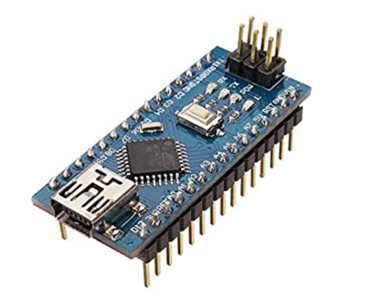
1. An Arduino NANO development board
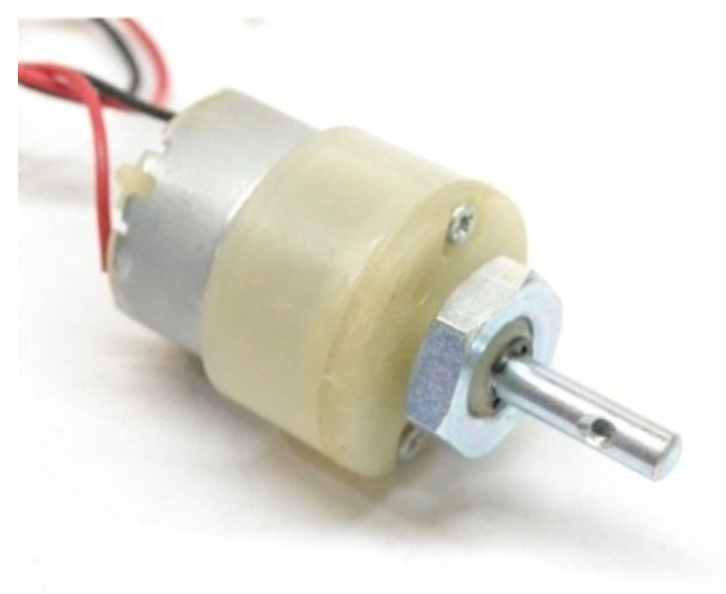
2. A12-V DC motor
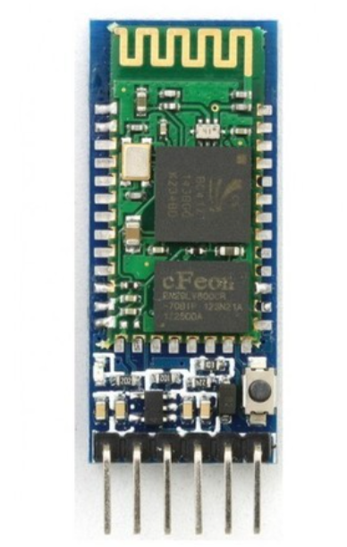
3. An HC05 bluetooth module
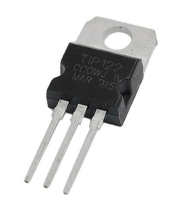
4. A TIP122 NPN Darlington transistors
5. A 330-ohm resistor
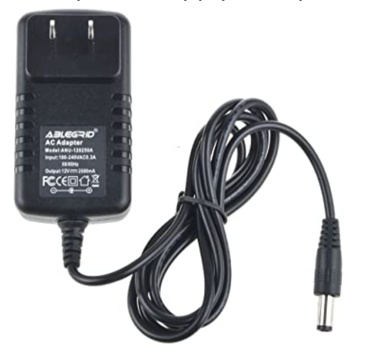
6. A 12-V power supply/adapter
Now, let’s build the circuit and then we’ll cover its operation.
Circuit diagram
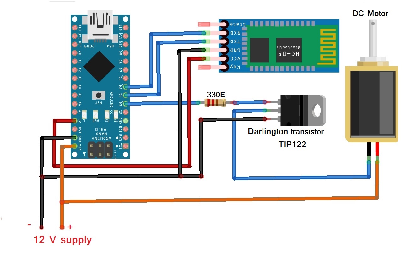
This circuit is built using only three components: Arduino NANO, the Bluetooth module HC05, and a Darlington transistor TIP122.
- The HC05 has four interfacing pins: Vcc, GND, Tx, and Rx. Here, the Vcc pin is given a 5-V supply from the Arduino board and the GND pin is connected with the board’s ground. The Tx and Rx pins are connected with Arduino’s pins D4 and D5, respectively.
- The PWM output pin D3 drives the 12-V DC motor using the TIP122. It’s connected to TIP122’s base terminal through the current limiting 330-ohm resistor.
- The TIP122 is used to amplify the current, providing the required current to the motor. The DC motor is connected between the collector output and the 12-V supply. The TIP122’s emitter terminal is connected to the ground.
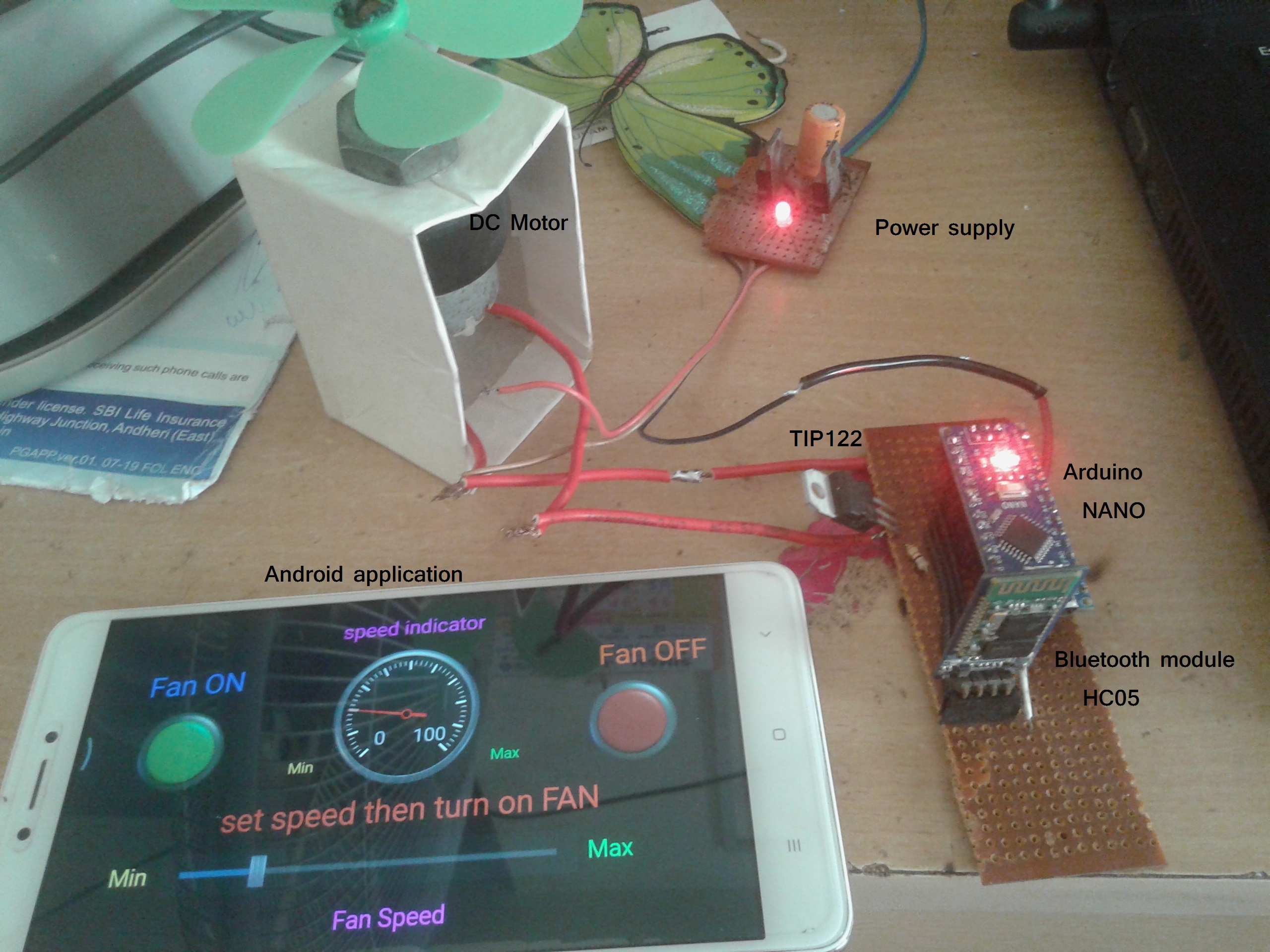
The circuit arrangement
Circuit operation
The circuit controls the speed of the 12-V DC motor using the Android app on a smartphone. The app sends the commands to start or stop the motor and to change the speed of the motor via the smartphone’s Bluetooth.
These commands are received by the HC05 module, which passes them on to the Arduino NANO via the Tx and Rx pins. As per the commands sent over, Arduino will run or stop the DC motor, or vary its speed from minimum to maximum.
Arduino generates a PWM signal on its D3 pin to run or stop the motor or to vary the motor speed. To stop the motor, the pulse width on the pin D3 is 0 (0%). And to run the motor at full speed, it’s 255 (100%). So, as Arduino changes the pulse width on its D3 pin, the motor speed changes from min to max — or vice versa.
Arduino can also send a change in motor speed (0 to 100 %) from the HC05 module to the smartphone’s app. The Android app will then display this motor speed value on an analog dial (or speed dial).
The Android app
The Android application is built using the“Bluetooth Electronics” application, which is available for free on Google Play.
First, download and install the “Bluetooth Electronics” app on your Android phone and open it. It will ask if you want to turn “ON” the device’s Bluetooth. Allow it to do so. Once the app starts, you’ll see a few readymade control panels that control Arduino-based projects.
Perhaps the most interesting feature of this app: it allows users to build a customized panel to control Arduino projects.
Let’s build a customized panel to control the DC motor speed.
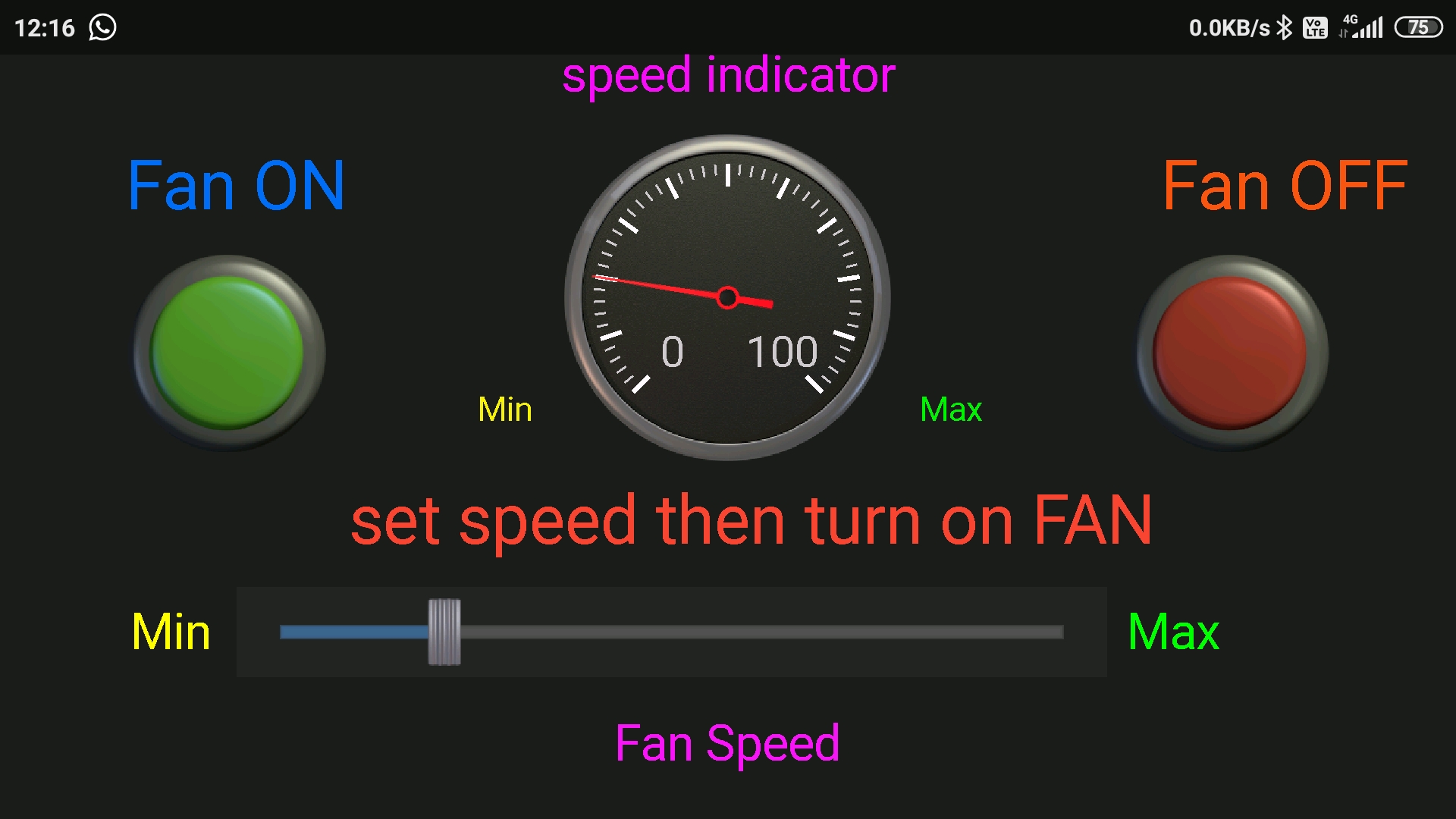
The panel consists of a green and red button to turn the mother “ON” or “OFF.” It also has one slider to vary the motor speed and one dial to view the motor speed.
Here’s how to make the panel:
1. Select one green button. Then, go to the right corner of the screen and edit the button properties as follows:
Press Text : N
Release Text :
2. Choose the text size with either a small or medium font, and write “Motor ON.”
3. Select one red button and edit its properties as follows:
Press Text : F
Release Text :
4. Choose the text size with either a small or medium font, and write “Motor OFF.”
5. Select the biggest slider from the slider options and edit its properties as follows:
Min Value : 100
Max value : 255
Select “Send on slider change”
String starts with : *
String Ends with : #
6. Go to the indicator options and choose the analog dial. Edit its properties like this:
Receive character : D
Min Text : 0
Max Text : 100
min value : 0
max value : 100
leave default all others
7. Write all of the other text, such as “min”, “max”, “motor speed”, “speed indicator” etc., as you choose.
And that’s it! Your android app is ready to control the DC motor speed.
Running the project
1. Connect the circuit as per the given schematic on the bread board or on the general purpose PCB.
2. Give the 12-V power supply to the circuit.
3. Initially, the motor is not moving and is in the stop position. The HC05 module will start blinking to indicate it’s searching for the device.
4. Start the “Bluetooth electronics” application in your smartphone, ensuring the Bluetooth is “ON.”
5. Press the connect button so it searches for the HC05 module. When the device is found, select “HC05” and press connect. When doing so for this first time, you’ll have to enter passkey “1234.”
6. Once the HC05 is connected, press done.
7. Now, you can run your panel.
8. From the panel, press the green button to start the motor or the red button to stop it.
9. While the motor is running, change the slider to vary the motor speed.
10. As the slider moves, the speed dial will indicate the motor speed (from 0 to 100%).
Software program:
This project works because of the software program that’s downloaded in Arduino’s microcontroller ATMega328. The program is written in C language using the Arduino IDE software.
#include<SoftwareSerial.h>
SoftwareSerial bt_ser(4,5);
char c[6];
int i=0,speed_value=150,send_value;
bool fan_on_flag = false;
void setup()
{
Serial.begin(9600);
bt_ser.begin(9600);
analogWrite(3,0);
Serial.println(“DC Motor speed control using android app”);
}
void loop()
{
while(bt_ser.available())
{
if(bt_ser.available()>0)
{
c[i] = bt_ser.read();
Serial.print(c[i]);
i++;
}
if(c[i-1]==’N’)
{
analogWrite(3,speed_value);
fan_on_flag = true;
i=0;
}
if(c[i-1]==’F’)
{
analogWrite(3,0);
fan_on_flag = false;
i=0;
}
if(c[i-1]==’#’)
{
speed_value = (c[1]-48)*100+(c[2]-48)*10+(c[3]-48)*1;
send_value = map(speed_value,100,255,0,100);
if(fan_on_flag) analogWrite(3,speed_value);
Serial.print(speed_value);
Serial.print(‘\t’);
Serial.println(send_value);
bt_ser.print(“*D”);
bt_ser.print(send_value);
bt_ser.print(‘*’);
i=0;
}
}
}
You may also like:


Filed Under: Electronic Projects, How to, More Editor's Picks

Questions related to this article?
👉Ask and discuss on Electro-Tech-Online.com and EDAboard.com forums.
Tell Us What You Think!!
You must be logged in to post a comment.