In this tutorial, a constant voltage charger for the 12V lead acid battery will be designed. The lead-acid batteries can be charged in different ways or modes. In this tutorial, a constant voltage charger will be designed for charging the lead-acid battery. The battery is required to be supplied limited current which saturates once the peak terminal voltage is achieved in the charging process. Depending on the per cell voltage of the 12V battery, the maximum rated voltage of the battery varies from 13.5 V to 14.6 V.
In this tutorial, the charger circuit is designed for charging a lead acid battery having peak terminal voltage of 14.4 V. So, this charger circuit charges the battery with a constant voltage of 14.4 V and provides a maximum current of 1.25 A.
Components Required –

Fig. 1: List of Components required for 12V Lead-Acid Battery Constant Voltage Limited Current Charger for UPS
Block Diagram –

Fig. 2: Block Diagram of LM317 based Lead Acid Battery Charger
Circuit Connections –
This charger is easy to design and has the following circuit blocks where each block serves a specific purpose –
1. AC to AC conversion –
The voltage of Main Supplies (Electricity fed by the intermediate transformer after stepping down line voltage from generating station) is approximately 220-230V AC. This voltage needs to be stepped down by using a step-down transformer to the required voltage level. A step-down transformer having a rating of 18V-0-18V/2A is used in the circuit. It is capable of providing 2A current which is well suited for an application having a current requirement of 1.25 A. This transformer step downs the main line voltage to 18V AC.
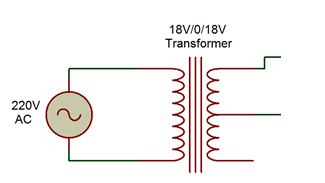
Fig. 3: Circuit Diagram for Stepping Down Mains Supply
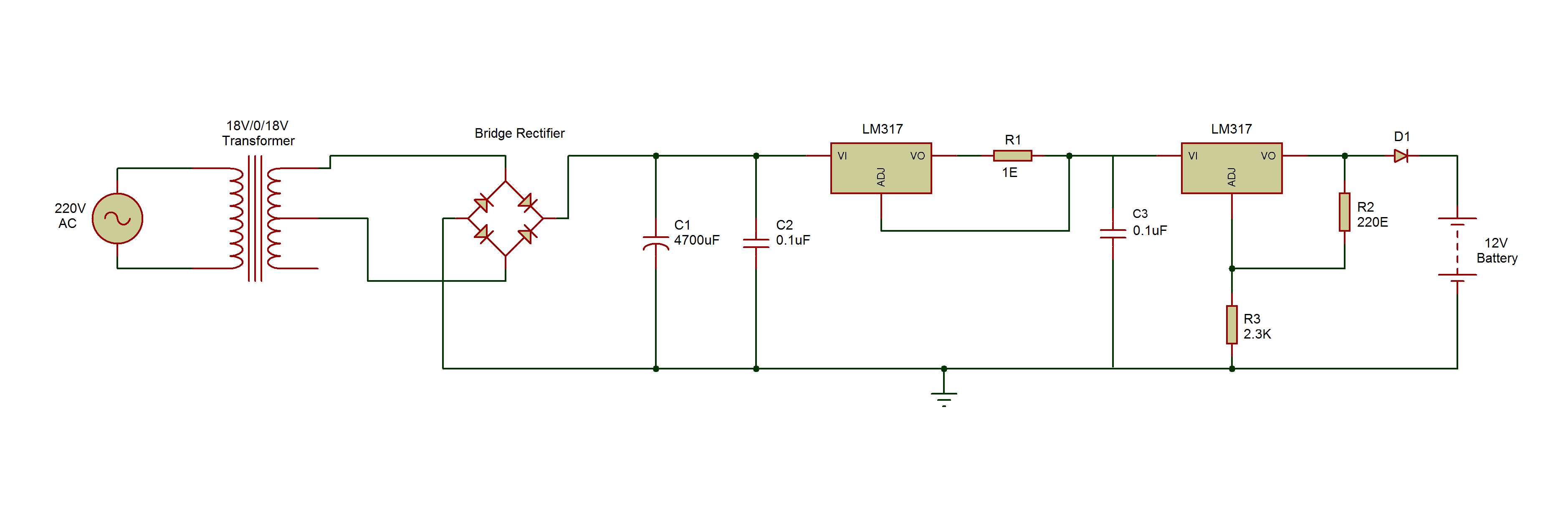
It is important that the current rating of the step-down transformer and bridge rectifier diode must be greater than or equal to the required current at the output. Otherwise, it will be unable to supply the required current at the output. The voltage rating of the step-down transformer should be greater than the maximum required output voltage. This is due to the fact that, the LM317 IC used in the circuit takes a voltage drop of around 2V. In this circuit, two LM317 ICs are used so input voltage from transformer must be 4 to 5V greater than the maximum output voltage required and should be in the limit of the input voltage of LM317.
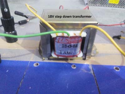
Fig. 4: Image of 18-0-18V Step down transformer
2. AC to DC conversion or Rectification –
The stepped down AC voltage needs to be converted to DC voltage through rectification. The rectification is the process of converting AC voltage to DC voltage. There are two ways to convert an AC signal to the DC one. One is half wave rectification and another is full wave rectification. In this circuit, a full wave bridge rectifier is used for converting the 18V AC to 18V DC. The full wave rectification is more efficient than half wave rectification since it provide complete use of both the negative and positive sides of AC signal.
In full wave bridge rectifier configuration, four diodes are connected in such a way that current flows through them in only one direction resulting in a DC signal at the output. During full wave rectification, at a time two diodes become forward biased and another two diodes get reverse biased.

Fig. 5: Image of KBPC3510 Full Bridge Rectifier
In this circuit, KBPC-3510 is used as bridge rectifier. It is a single phase bridge rectifier that has a peak reverse voltage of 1000 V and average rectified output current of 35 A. So, it can easily block 18 V in reverse bias and allow 1.25 A current in forward bias situation. Instead of using KBPC-3510 directly, four SR560 diodes can also be used to make a full wave bridge rectifier that will allow maximum 1.5 A current and in reversed bias will be capable of blocking 18V supply.
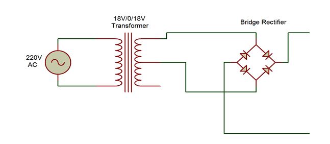
Fig. 6: Circuit Diagram of Full Bridge Rectifier
3. Smoothening –
Smoothening is the process of filtering the DC signal by using a capacitor. The output from the full-wave rectifier is not a steady DC voltage. The output from the rectifier has double the frequency of main supplies but still containing ripples. Therefore, it needs to be smoothed by connecting a capacitor in parallel to the output of full wave rectifier. The capacitor charges and discharges during a cycle giving a steady DC voltage as output. So a capacitor (shown as C1 in the circuit diagram) is connected at the output of full bridge rectifier.
A ceramic capacitor ( shown as C2 in the circuit diagram) is connected in parallel to this electrolytic capacitor to decrease the equivalent output impedance or ESR. At the output of the charging circuit, there should be a capacitor for absorbing any unwanted ripples. But in this circuit, the battery is connected at the output, which acts like a capacitor itself. So there is no need to connect any capacitor at the output terminal of the charging circuit.

Fig. 7: Circuit Diagram of Smoothing Capacitors
The capacitor used in the circuit must be of higher voltage rating than the input supply voltage. Otherwise, the capacitor will start leaking the current due to the excess voltage at its plates and will burst out. It should be made sure that the filter capacitor should be discharged before working on a DC power supply. For this the capacitor should be with a screw driver wearing insulated gloves.

Fig. 8: Image of Smoothing Capacitor
4. Voltage Regulation using LM317 –
For designing a constant voltage charger for 12V lead-acid battery, a constant voltage source and a current limiter are required. The voltage source should provide a constant voltage equal to the maximum voltage rating of the battery. Considering the charging current of the lead acid battery it should be half or less than the maximum current rating of the battery. In this circuit, LM317 IC is used as constant voltage source of 14.4 V as the 12V battery used in the circuit has a peak terminal voltage of 14.4 V. For charging current, another LM317 IC is used as a constant current source. This current source will limit the charging current to 1.25A so the battery never draws current greater than this value.
LM317 is used for the voltage regulation. LM317 is a monolithic positive voltage regulator IC. Being monolithic, all the components are inbuilt on the same semiconductor chip making the IC small in size having less power consumption and low cost. The IC has three pins – 1) Input pin where maximum 40 V DC can be supplied, 2) Output pin which provides output voltage in the range of 1.25 V to 37 V and 3) Adjust pin which is used to vary the output voltage corresponding to the applied input voltage. For input up to 40 V, the output can vary from 1.25 V to 37 V.
For using the IC as a constant voltage source the resistive voltage divider circuit is used between the output pin and ground. The voltage divider circuit has one programming resistor (Rp) and another is output set resistor (Rs). By taking a perfect ratio of programming resistor and output resistor a desired output voltage can be drawn. The output voltage of the IC Vout is given by the following equation –
Vout = 1.25*(1 + (Rs/Rp) (from the datasheet of LM317)
The typical value of Programming resistor (Rp) can be from 220E to 240E for the stability of the regulator circuit. In this circuit, the value of Programming Resistor (Rp) is taken 220E. As the output voltage should be 14.4 V, the value of the output set resistor (Rs) can be determined as follow –
Desired output voltage, Vout= 14.4 V
Output set resistor, Rp = 220E
Putting values of Vout and Rp in the above equation,
14.4 = 1.25*(1+ (Rs/220)
So, the value of output set resistor is –
Rs = 2.3K (approx.)

Fig. 9: Circuit Diagram of LM317 IC based constant voltage source
For designing a current limiter circuit, a constant current source need to be designed. In the circuit another LM317 is used as a constant current source. For this, a resistance (Rc) is connected to the IC from the output to adjustment pin. A ceramic capacitor ( shown as C3 in the circuit diagram) is connected at the output of this IC to avoid any voltage spike and unwanted noise.
In a normal state when there is the constant demand of current at the output then 317 will maintain a voltage of 1.25V at its adjust terminal. Therefore, the voltage across the resistor Rc is also 1.25V. As the current demand changes at the output, it should also change the voltage drop across resistor Rc but LM317 will adjust the output voltage to compensate a constant 1.25V drop across the resistor Rc.
Hence, the voltage across Rc is always 1.25V. Therefore a constant current flows through this resistor. The constant current output by the IC can be calculated by the following equation –
I= 1.25/Rc (from the datasheet of LM317)
Here I is the constant current at the output
The value of constant current can be changed by changing the value of resistor Rc. As LM317 can provide a maximum current of 1.5 A so the value of Rc cannot be less than 0.83E.
A charging circuit for a maximum charging current of 1.25 A has to be designed. So by using equation stated above, the value of resistor Rc for 1.25A current can be calculated as follow –
I= 1.25/Rc
By putting I= 1.25A,
Rc= 1E
In the selection of any resistor, there are two parameters that should be considered – one is its resistance and another is its wattage. The wattage depends upon the maximum current which flows through the resistor. If a low watt resistor is taken then high current will heat up the resistor and cause damage to it. In this circuit, the maximum current that flows from the resistor Rc is 1.25 A. So the wattage of the resistor can be calculated as follow –
Power = (voltage drop across Rc )*(maximum current across Rc)
Power = 1.25*1.25
Power = 1.6W(approx.)
Therefore, the maximum power which is dissipated by the resistor Rc is 1.6W. That is why, a resistor of 2W rating is used in the circuit. In this circuit, the resistor Rc is connected as resistor R1.

Fig. 10: Circuit Diagram of LM317 IC based constant current source
In this circuit, LM317 is to be used as the current limiter. The first LM317 IC in the circuit acting as constant current source, provides the input voltage to the next LM317 IC which is acting as a constant voltage source. So the output current or charging current is controlled by the first LM317 IC. So, the battery draws current upto 1.25 A. Therefore the constant current source acts like a current limiter in this circuit.

Fig. 11: Circuit Diagram of LM317 IC based Constant Voltage Constant Current Source
Initially, the current demand of the battery is more since the battery is fully discharged. Due to high current the LM317 IC starts heating up and IC takes more drop across it which reduces the output voltage. So, it is recommended to use a heat sink to aid cooling to the IC and increase its. Along with the heat sink, heat plaster should also be used to add extra cooling to the IC by applying the plaster to both sides of the IC. A cooling fan can also be used for heat dissipation which can blow off the extra heat from the IC. The heat sink is also a conductor so the IC pins should never be short with the heat sink as this can damage the IC.
5. Protection diode –
A diode D1 is used at the output to block any reverse current from the battery when the circuit is in off state. This saves the LM317 IC from any back current.

Fig. 12: Circuit Diagram of Protection Diode
The charger circuit act like a constant voltage source of 14.4 V with a current limit of 1.25 A.
How the circuit works –
Lead Acid batteries are one of the commonly used batteries. These batteries are used in high current demand applications and are preferred due to reasonable power to weight ratio. These low cost batteries are easy to design and manufacture. These batteries can be charged through following three methods –
1. Constant current method :– In this type of charging a constant current is provided to the battery by adjusting the voltage. This method requires an intelligent voltage sensor circuitry so that it senses the voltage and stops the battery charging when the battery voltage reaches the maximum rated voltage.
2. Constant voltage method :– In this method, a constant voltage is provided to the battery by limiting the charging current of the battery. When the battery is fully charged then it draws very less current (about 1-3% of battery current rating) which indicates that the battery is fully charged.
3. Constant current – Constant voltage method :- This is the combination of both the above methods. Initially, a constant current is provided until the battery reaches the maximum rated voltage. Then, the charging current reduces and the charging circuit switches to a constant voltage mode. In this mode, the charging circuit only provides the current which is required to maintain the maximum voltage of the battery.
As a result, current starts decaying as the time passes and reaches a saturation value. Therefore, this type of charging circuit requires some intelligent circuitry which can monitor the charging current as well as the terminal voltage of the battery. So that this intelligent circuitry could switch the charging circuit from constant current mode to constant voltage mode. When the charging current is about 1 to 3% of the rated current of the battery, then the circuitry stops the charging by sensing the current.
These charging methods have their own pros and cons. The constant voltage method is a cheap and effective charging method while constant current constant voltage method is most effective method but requires a bit complex circuitry incurring additional cost. The comparison between these charging methods is summarized in the following table –

Fig. 13: Table listing pros and cons of constant current, constant voltage and constant current constant voltage charging
Considering the comparison of the charging methods, a constant voltage charger is the most reasonable option which gives fast charging without need of complex circuitry. In this circuit, a constant voltage constant current charger is designed using LM317 ICs as constant voltage source as well as current limiting constant current source.
Testing –
Once the circuit is assembled, its output voltage and current should be measured for checking the efficiency and stability of the circuit. The following observations were taken during the testing of the circuit –
Practical Output set voltage, Vout = 14.37 V (when battery is not connected to the output)
For testing the charging circuit a 12V/6A lead acid battery is used for charging. Initially, the battery voltage is 13 V and after charging it to about 7 to 8 hours, the battery is charged to 13.5 V. The following observations were noted during the charging of the battery –

Fig. 14: Table listing output characterstics of Lead-Acid Battery Constant Voltage Limited Current Charger
From the above observations, it is clear that the output set voltage is less than 14.37 V. This drop in voltage is due to the voltage drop across the diode D1 which is connected in series at the output. As the current flowing through the diode D1 decreases the diode takes low voltage drop across it which can be seen from the above table. The minimum voltage drop across the diode D1 (SR560) is 0.15 V as per the datasheet so the output set voltage can be increased upto 14.25 V when the current drawn by the battery is negligible(less than 60 mA)
During charging the battery for about 7 to 8 hours, in the last 1 and 2 hours of charging, the battery is charged from a constant current of around 67 mA which is approx. 1% of the battery maximum current rating(6 A). When the battery current decreases below 67 mA then the battery is fully charged.

Fig. 15: Prototype of 12V Lead-Acid Battery Constant Voltage Limited Current Charger designed for UPS
This charging circuit can only charge 12V lead acid battery with a current rating greater than or equal to 2000 mA. The circuit has the following advantages –
• Adjustable charging current –
This charging circuit provides a maximum charging current of 1.25 A but the charging current can be adjusted from 10mA to 1500 mA by changing the value of resistor R1(as explained when using LM317 as constant current source)
• Adjustable output set voltage-
The output set voltage of this charging circuit is 14.4 V and it can vary from 1.25V to 37V by changing the value of resistor R3 (as explained when using LM317 as constant voltage source)
This is a basic charger circuit using only two LM317 ICs. This circuit should be used only to charge a lead acid battery which is having 2000 mA or more current rating. It should be taken care that the output should not be shorted as it will cause the battery terminals to short which may result in bursting the battery and causing a fire accident. There can be loose connections that may result in no voltage or abrupt voltage at the output. The circuit has been assembled on a handmade breadboard which is similar to any ordinary breadboard but is designed for high power applications.
You may also like:
Circuit Diagrams
Project Video
Filed Under: Electronic Projects, Featured Contributions
Filed Under: Electronic Projects, Featured Contributions






Questions related to this article?
👉Ask and discuss on Electro-Tech-Online.com and EDAboard.com forums.
Tell Us What You Think!!
You must be logged in to post a comment.