The decorative Light Fountains are readily available in market as gift articles. Here the given project demonstrates how to operate it using TV remote (or any other remote of AC or Music System etc.) To make it Remote Operated it needs to be modified, inside its Internal Circuits and there is also a need to build one Simple Circuit using IR Sensor to sense IR Remote Signal.
The readily available decorative Light Fountains are like this
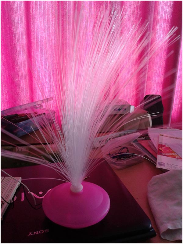
Fig. 2: Image Of decorative Light Fountains
First detach Optical Fiber Cables. You will see 3 different color LEDs inside – RED, GREEN, BLUE.
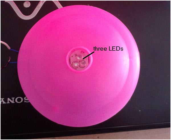
Fig. 3: Image Of LEDs inside Light Fountains
Now remove top cap to see the Internal Circuit. As shown in the image, inside there is one Simple Circuit with 3 LEDs on top and one COB at bottom (Not Visible in the given Image). The Circuit has only Four External Connections – 2 for Power Supply (through battery cells as shown) and 2 for push button switch. Just disconnect the connections for push button switch as shown. These two connections will be connected to IR Sensor Circuit.
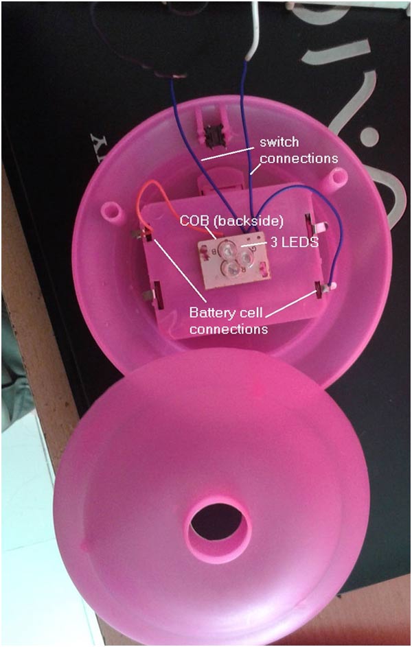
Fig. 4: Iamge Of Internal Circuit Of decorative Light Fountains
IR Sensor Circuit
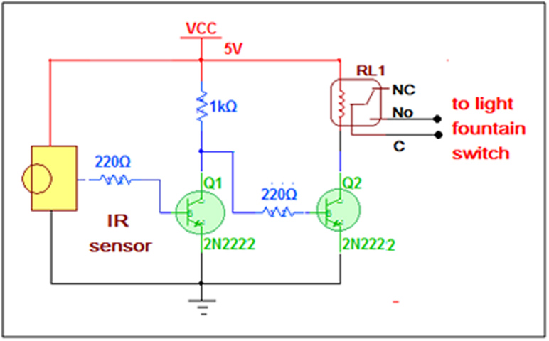
The circuit is very simple, built using IR Sensor TSOP1738, two NPN Transistors and one C/O relay.
Kindly refer Circuit Diagram Tab for the Circuit at the top.
Circuit Description
The output of the sensor is connected to base input of NPN Transistor Q1. Both Q1 and Q2 Transistors are connected in switch configuration. The Relay Coil is connected between Vcc and Collector of Q2 as shown. The common (C) and normally open (NO) terminals are connected with the switch terminals of Light Fountain. So now instead of push button switch the relay switch is connected.
Here is the image of circuit built on bread board
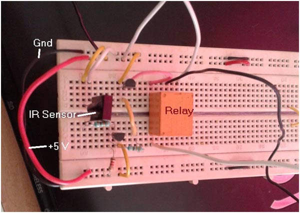
Fig. 5: Prototype Of Light Fountain On Breadboard
Circuit Operation
Normally, sensor output is high. So Q1 transistor is ON. So its collector output is low. Because its output is an input to Q2, Q2 is OFF. So relay is also OFF (de-energized). When IR Signal falls on Sensor, its output goes low. So Q1 becomes OFF. That makes Q2 ON. So relay energizes and it switches ON. This makes momentarily contact between C and NO terminals. This contact triggers COB and makes light fountain ON.
Every time when any of the buttons is pressed from any TV remote the relay contact triggers Light Fountain and it becomes ON. The COB performs different functions on every trigger. Like
· It switches ON and OFF LEDs on alternate trigger
· It switches alternate LEDs like first only RED, then only GREEN, then only BLUE, then RED-GREEN and like wise
· It also blinks all 3 LEDs with different effects to generate great overall lightning effect
Here is the image of complete circuit setup with Light Fountain
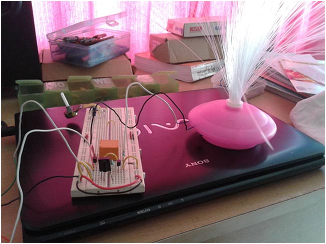
Fig. 6: Image Of Complete Circuit Setup Of Light Fountain
You may also like:
Circuit Diagrams
Project Components
Project Video
Filed Under: Electronic Projects, More Editor's Picks
Filed Under: Electronic Projects, More Editor's Picks






Questions related to this article?
👉Ask and discuss on Electro-Tech-Online.com and EDAboard.com forums.
Tell Us What You Think!!
You must be logged in to post a comment.