Engineers Garage

  • Projects and Tutorials
    • Circuit Design
    • Electronic Projects
      • 8051
      • Arduino
      • ARM
      • AVR
      • PIC
      • Raspberry pi
      • STM32
    • Tutorials
    • Components
  • Articles
    • Tech Articles
    • Insight
    • Invention Stories
    • How to
    • What Is
  • News
    • EE Design News
    • DIY Reviews
    • Guest Post
    • Sponsored Content
  • Forums
    • EDABoard.com
    • Electro-Tech-Online
    • EG Forum Archive
  • Digi-Key Store
    • Cables, Wires
    • Connectors, Interconnect
    • Discrete
    • Electromechanical
    • Embedded Computers
    • Enclosures, Hardware, Office
    • Integrated Circuits (ICs)
    • Isolators
    • LED/Optoelectronics
    • Passive
    • Power, Circuit Protection
    • Programmers
    • RF, Wireless
    • Semiconductors
    • Sensors, Transducers
    • Test Products
    • Tools
  • EE Resources
    • DesignFast
    • LEAP Awards
    • Oscilloscope Product Finder
    • Video
    • White Papers
    • Webinars
  • EE Learning Center
  • Women in Engineering

Keypad Controlled And Industrial Gas Monitoring Wireless Robot

February 15, 2021 By Hai Prasaath K

In factories and industries it is common to deal with the use of harmful and poisonous gases. There are situations in which the concentration and volume of these type of gases need to be monitored in an apparatus. Because these gases can be harmful to humans, it is not safe to employ humans for such tasks. So, robots can be used monitor different parameters related to the use of such gases in an apparatus or gas filled chamber. In this tutorial, a wireless robot is designed which can move inside a chamber or well and detect the level of concentration of the gas at the spot. 
The X-bee modules are used to connect the robot wirelessly with a remote control. X-bee is a Zigbee module from Digi International. Zig-Bee is a standard wireless communication technology that transfers data over ISM radio bands. It operates on 2.4 GHz worldwide and at other ISM frequencies in select countries. The communication protocol is commonly used for making personal area networks for applications like home automation, wireless office networks and sensor based data networks. The Zig-Bee modules are commonly used for connecting low power embedded devices that need to operate in a small area at low data rates. A Zig-Bee module operating on 2.4 GHz band has the data rate of 250 Kbps. With X-bee used for wireless connectivity, the robot can be moved from 30 Meter to 100 Meter away from the remote control.  
The remote control has a keypad which allows controlling the movement of the robot and send instructions to take measurements of the concentration level. There is also an LCD display on the remote which allows monitoring the measurements taken. The robot is a surface moving robot with a castor and two wheel body. The robot is equipped with MQ-135 and MQ-7 gas sensors to monitor the presence and concentration of gases.  The MQ-7 is used to measure the concentration of carbon monoxide in the air while MQ-135 is used to monitor the concentration of combustible gases. The robot is driven on two wheels with L293D motor driver IC used to control the attached geared DC motors. The X-bee module is used to connect the robot with the remote control. 
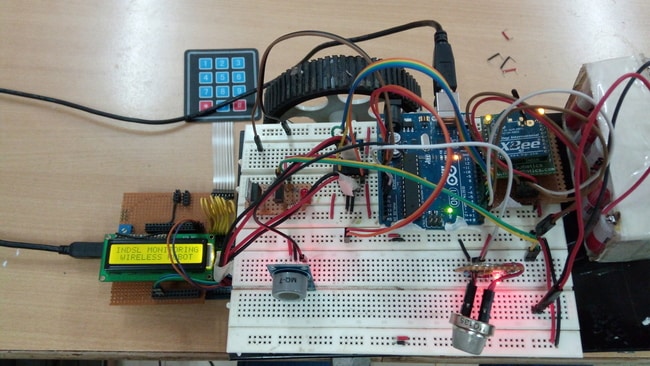
Prototype of X-bee based Keypad controlled Wireless Arduino Robot for Gas Monitoring
Fig. 1: Prototype of X-bee based Keypad controlled Wireless Arduino Robot for Gas Monitoring
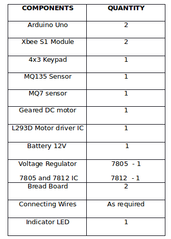
Components Required :
List of Components required for X-bee based Keypad controlled Wireless Arduino Robot for Gas Monitoring
Fig. 2: List of components required for X-bee based Keypad controlled Wireless Arduino Robot for Gas Monitoring
Block Diagram :
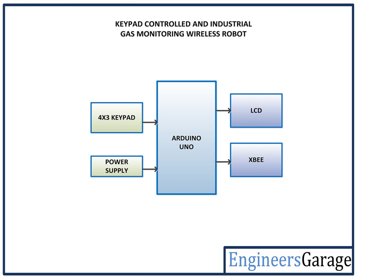
The circuit of the remote control of the robot can be represented by the following block diagram – 
Block Diagram of Remote Control for X-bee based Keypad controlled Gas Monitoring Wireless Arduino Robot
Fig. 3: Block Diagram of Remote Control for X-bee based Keypad controlled Gas Monitoring Wireless Arduino Robot

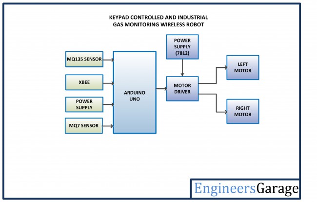
The control circuit of the robot (mounted on it) can be represented by the following block diagram –
Block Diagram of Control Circuitry for X-bee based Keypad controlled Gas Monitoring Wireless Arduino Robot
Fig. 4: Block Diagram of Control Circuitry for X-bee based Keypad controlled Gas Monitoring Wireless Arduino Robot


Circuit Connections – 
There are two circuits used in the project – one is the remote control circuit and other is the control circuit mounted on the robot. The remote circuit is built using Arduino Mega, 4X3 Keypad, 16X2 character LCD and X-bee module. The control circuit of the robot which is mounted on its body comprises of Arduino UNO, MQ-135 sensor, MQ-7 sensor, X-bee module, L293D motor driver IC and geared DC motors. 
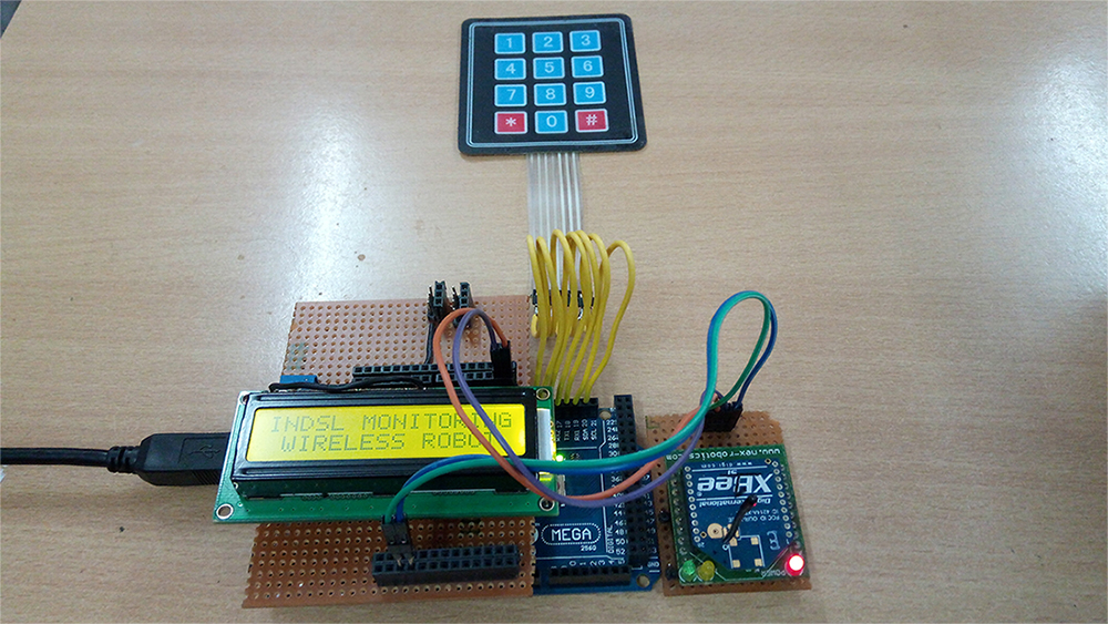
The remote circuit has the following circuit connections – 
Image of Remote Control for X-bee based Keypad controlled Gas Monitoring Wireless Arduino Robot
Fig. 5: Image of Remote Control for X-bee based Keypad controlled Gas Monitoring Wireless Arduino Robot

Arduino Mega – Arduino Mega is one of the microcontroller boards available on the Arduino platform. This controller board has Atmega 1280 as the sitting MCU and has 128 Kb flash memory, 4 Kb EEPROM, 8 Kb SRAM, onboard UART, SPI and I2C interfaces. The board has 56 GPIO pins of which 15 pins can be used for 8-bit PWM output. There are 16 analog input pins available on the board as well. This is a bigger controller board available from the Arduino and is generally used when number of sensors or components required to be interfaced is large. In the remote circuit, 15 pins of the board are utilized where 6 pins are used to interface character LCD, 7 pins are used to interface keypad and Rx and Tx pins are used to connect with the X-bee module. 
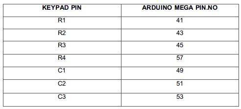
4X3 Keypad – A 4X3 keypad is used in the project. The keypad has 12 buttons arranged in 4 rows and 3 columns. This is a numeric keypad which is used to control the movement of the robot and send instruction to take measurement of the gas concentration. The rows and columns of the keypad are interfaced with the Arduino in the following scheme – 
Table Listing Circuit Connections between Arduino Mega and Keypad
Fig. 6: Table liisting circuit connections between Arduino Mega and Keypad
Such matrix keypad operate by conducting between a unique row and column on the press of a switch. Either of the rows or columns are made digital output while the other remaining (either rows or columns) are made digital input. Suppose the rows are set digital output and columns as digital input. Now, the controller loops through the rows made digital output by setting them HIGH or LOW one after the other and simultaneously check for reception of the same logic on the columns. So, at a time a unique row is set HIGH or LOW while other rows are set inversely and on press of a key the same logic is received at a unique column. This unique combination of a row and a column allows identifying the key pressed. 
16X2 Character LCD – The 16X2 LCD display is used to monitor the sensor values sent by the wireless robot. It is interfaced with the Arduino MEGA by connecting its data pins D4 to D5 with pins 6 down to 3 of the controller respectively. The RS and E pins of the LCD are connected to pins 13 and 12 of the controller respectively. The RW pin of the LCD module is connected to the ground. The circuit connections of the character LCD with the Arduino board are summarized in the following table – 
Table Listing Circuit Connections between Arduino Uno and Character LCD
Fig. 7: Table listing circuit connections between Arduino Uno and Character LCD
X-bee module – X-Bee is a Zigbee module from Digi international. Zigbee is a wireless communication module which use IEEE 802.15.4 standard. The 802.15.4 is a IEEE standard for low power applications of radio frequency. It used in many products for wireless communication functionality. It can be used as a transmitter and receiver both. It uses serial communication to send and receive data. It has two series, series 1 and series 2.  Series 1 is comparatively easy to use and it is recommended for beginners. In this project Series 1 X-bee module is used. The Series 1 Zigbee module cannot work in mesh network. That means it cannot talk to more than one Zigbee at a time. Learn more about Zigbee technology. 
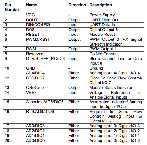
The series 1 X-bee is a 20-pin module with the following pin configuration – 
Table Listing Pin Configuration of Xbee Module
Fig. 8: Table listing pin configuration of Xbee Module
The module can be connected with a controller board using UART. The module can be connected with the Arduino by connecting its DOUT (UART Data Out) or TX pin with RX pin of the Arduino and DIN (UART Data In) or RX pin with the TX pin of the Arduino. The VCC and Ground pins of the module must be connected to common VCC and ground. The X-Bee module used in the remote circuit is configured to work as both RF data transmitter as well as receiver. The remote needs to transmit control commands while it needs to receive sensor data from the robot. 
Power Supply – All the components of the remote circuit requires a 5V DC supply. The Arduino board is powered with 5V by a USB cable. The other components draw power from 5V Vout pin of Arduino board.
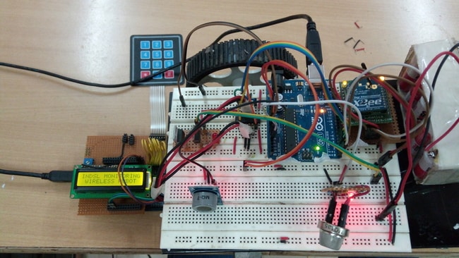
The control circuitry mounted on the robot is assembled from the following components – 
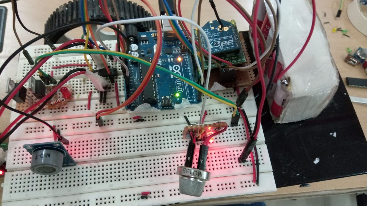
Image of Control Circuitry for X-bee based Keypad controlled Gas Monitoring Wireless Arduino Robot
Fig. 9: Image of Control Circuitry for X-bee based Keypad controlled Gas Monitoring Wireless Arduino Robot

Arduino UNO – Arduino UNO is one of the most popular prototyping boards. It is used frequently in robotic applications as it is small in size and packed with rich features. The board comes with built-in Arduino boot loader. It is an Atmega 328 based controller board which has 14 GPIO pins, 6 PWM pins, 6 Analog inputs and on board UART, SPI and TWI interfaces. In this control circuit, 8 pins of the board are utilized. There are 4 pins used to connect with the input pins of the motor driver IC.  The two pins RX and TX of the board are used to interface the X-bee module and establish serial communication over USART. The analog input pins A0 and A1 are used to interface the MQ-7 and MQ-135 sensors. Learn more about Arduino UNO from here. 
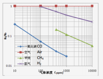
MQ-7 Gas Sensor – MQ-7 is a carbon monoxide sensor used to measure the concentration of CO gas in air between the range of 20 PPM to 2000 PPM. The sensor uses SnO2 as the sensitive material which has low conductivity in clean air but has high conductivity when the concentration of Carbon monoxide is higher in the air. The sensor is used as industrial CO gas alarm and portable CO gas detector. 
Graph showing Sensitivity Curve of MQ-7 CO Sensor
Fig. 10: Graph showing Sensitivity Curve of MQ-7 CO Sensor

From the sensitivity curve of the sensor, it can be seen that the resistance of the sensor decreases as the concentration of the target gas is increased in PPM while for clean air its resistance remains constant. In the graph, the Rs is the resistance in target gas and Ro is the resistance in clean air. The graph is shown for CO, CH4 and H2 gases.
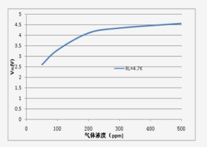
Graph showing Analog Voltage Output Curve of MQ-7 CO Sensor
Fig. 11: Graph showing Analog Voltage Output Curve of MQ-7 CO Sensor
It can be seen that as the concentration of the target gas increases, the voltage output is also increased. The above graph has been taken for a load resistance of 4.7 KΩ. The sensor has four terminals – Ground, VCC, Digital Out and Analog Out. The VCC and Ground terminals of the sensor are connected to the common VCC and Ground. The Analog Output pin of the sensor is connected to the A0 pin of the Arduino. The analog output voltage from the sensor can be assumed directly proportional to the concentration of CO gas in PPM under standard conditions. The analog voltage is sensed from the sensor and converted to a digital value in range from 0 to 1023 by the inbuilt ADC channel of the controller. The digitized value is hence equal to the gas concentration in PPM. 
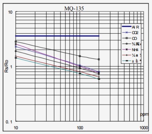
MQ-135 Sensor – MQ-135 is another gas sensor which is used to measure the concentration of combustible gases. It has lower conductivity in clean air while its conductivity increases with the presence of the combustible gases in the air. The sensor is highly sensitive to gases like Ammonia, Sulphide and Benzene steam. The sensor can detect the concentration of combustible gases in range from 100 PPM to 1000 PPM. 
Graph showing Sensitivity Curve of MQ-135 Sensor
Fig. 12: Graph showing Sensitivity Curve of MQ-135 Sensor
From the sensitivity curve of the sensor, it can be seen that the resistance of the sensor decreases as the concentration of the target gas is increased in PPM while for clean air its resistance remains constant. In the graph, the Rs is the resistance in target gas and Ro is the resistance in clean air. The graph is shown for Carbon dioxide, Carbon Monoxide and Ammonia. The sensitivity of this sensor can be adjusted and calibrated to detect specific concentration level of a target gas. The sensor has four terminals – Ground, VCC, Digital Out and Analog Out. The VCC and Ground terminals of the sensor are connected to the common VCC and Ground. The Analog Output pin of the sensor is connected to the A1 pin of the Arduino. The analog output voltage from the sensor can be assumed directly proportional to the concentration of CO2 gas in PPM under standard conditions. The analog voltage is sensed from the sensor and converted to a digital value in range from 0 to 1023 by the inbuilt ADC channel of the controller. The digitized value is hence equal to the gas concentration in PPM. 
X-Bee module – The X-Bee module used on the control circuit of the robot is also configured to work as both RF data receiver and transmitter. The module is interfaced with the Arduino by connecting its DOUT (UART Data Out) or TX pin with RX pin of the Arduino and DIN (UART Data In) or RX pin with the TX pin of the Arduino. The VCC and Ground pins of the module are connected to common VCC and ground.
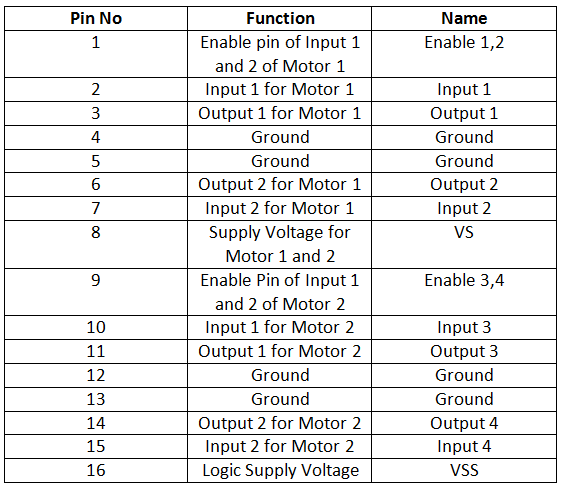
L293D motor Driver IC – The L293D is a dual H-bridge motor driver integrated circuit (IC). The Motor drivers act as current amplifiers since they take a low-current control signal and provide a higher-current signal. This higher current signal is used to drive the motors. It has 16 pins with following pin configuration: 

Table Listing Pin Configuration of L293D Motor Driver IC

Fig. 13: Table listing pin configuration of L293D Motor Driver IC
There are two DC motors used for making the robotic car. The DC motors are interfaced between pins 3 and 6 and pins 14 and 11 of the motor driver IC. 
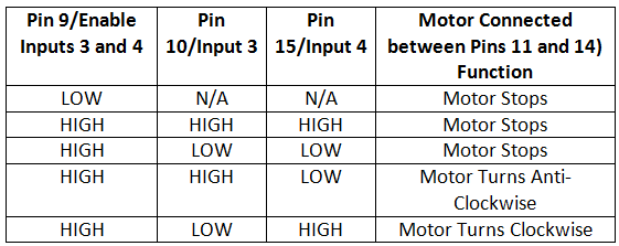
The L293D IC controls the DC Motors according to the following truth tables: 
Truth Table of L293D Motor Driver IC
Fig. 14: Truth Table of L293D Motor Driver IC
The pin 4, 5, 13 and 12 of the L293D are grounded while pin 1, 16 and 9 are connected to 5V DC and pin 8 is connected to 12V DC. The pins 15, 2, 7 and 10 of the motor driver IC are connected to pins 5, 2, 3 and 4 of the Arduino board. The DC motor attached to right wheel is connected to pins 11 and 14 while motor attached to left wheel is connected to pins 3 and 6 of the motor driver IC. The enable pins of the IC (pins 1 and 9) are hard wired to the 5V DC supply. 
Geared DC Motors – In this robot, 12V geared DC motors are attached to the wheels. Geared DC motors are available with wide range of RPM and Torque, which allow a robot to move based on the control signal it receives from the motor driver IC.
Power Supply – The Arduino UNO, X-Bee module, gas sensors  and logic supply pins of the motor driver IC requires 5V DC while the supply pin of the driver IC requires 12V DC. A 12V battery is used to power the robot. The supply from the battery is regulated to 5V and 12V using 7805 and 7812 ICs. The pin 1 of both the voltage regulator ICs is connected to the anode of the battery and pin 2 of both ICs is connected to ground. The respective voltage outputs are drawn from pin 3 of the respective voltage regulator ICs. An LED along with a 10K Ω pull-up resistor is also connected between common ground and output pin to get a visual hint of supply continuity. Despite using 12V battery, 7812 is used to provide a regulated and stable supply to the motor driver IC.   
How the circuit works – 
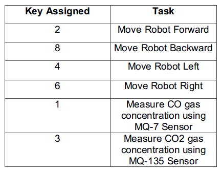
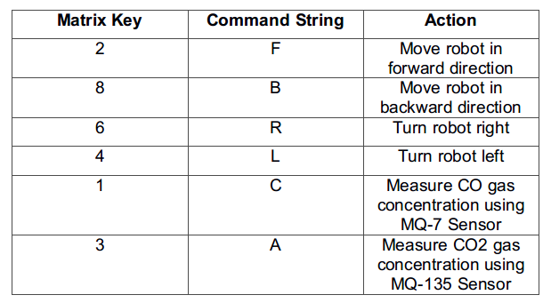
As the battery is attached to the robot, it gets ready to receive commands from the remote control. The remote control is powered by connecting it to a USB connection or a 5V regulated supply from a battery. As the remote is powered, some initial messages are flashed on it indication the application of the project. From the remote control, the commands can be passed by pressing the keypad keys. The following keys are assigned for the respective tasks in project – 
Table Listing Remote Key Assignments for Robot
Fig. 15: Table listing remote key assignments for Robot
When user presses a key, a string command is passed by the remote to the control circuitry of the robot using the X-bee interface. The following string characters are passed by the remote circuit to the receiver circuit of the robot on the press of the respective keys – 
Table Listing Command Strings for Remote Control of Robot
Fig. 16: Table listing command strings for remote control of robot
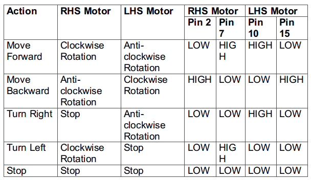
The command strings are read by the Arduino board of the receiver circuit with the help of the another X-bee module. On receiving a command, the Arduino board compares it with the command strings mentioned above and change digital logic at the pins connected to the input pins of the motor driver IC to perform the desired operation. The robot is moved forward, backward, left or right by implementing the following input logic at the motor driver pins –
Logic Table of L293D Motor Driver IC for Arduino Robot
Fig. 17: Logic Table of L293D motor driver IC for Arduino Robot
The input pins of the motor driver IC are connected to the Arduino pins and by changing the digital logic at the Arduino pins, respective logic is implemented at the input pins of the motor driver IC. 
So, the user can navigate the robot to the place where it has to measure the gas levels. Once the robot has reached that spot, the user needs to press the key 1 or 3 to pass the command for measuring concentration of CO or CO2 respectively. When command to measure the concentration of gas from MQ-7 or MQ-135 sensor is received, the Arduino board senses the voltage at the pin A0 or A1 respectively. The voltage is converted to a digital reading using in-built ADC channel and sent as string back to the remote circuit. The remote circuit receives the measured gas level as serial data from the X-bee module. The Arduino sketch of the remote circuit converts this string to an integer value and display it on the LCD display. 
Image of X-bee based Keypad controlled Wireless Arduino Robot for Gas Monitoring
Fig. 18: Image of X-bee based Keypad controlled Wireless Arduino Robot for Gas Monitoring

For activating the wireless connection between the robot and the remote circuit, it is important to configure the X-Bee modules on both sides. The CoolTerm terminal application is used to configure the X-Bee modules. In order to make PC to communicate directly with the Xbee, even arduino board can be used by removing the controller IC or an simple sketch can be uploaded to the arduino boards, which makes Xbee enabled to directly communicate with computer and not to the Arduino board. First of all the circuit connections between the X-Bee module and the Arduino must be made as mentioned above.  
Now follow the following steps – 
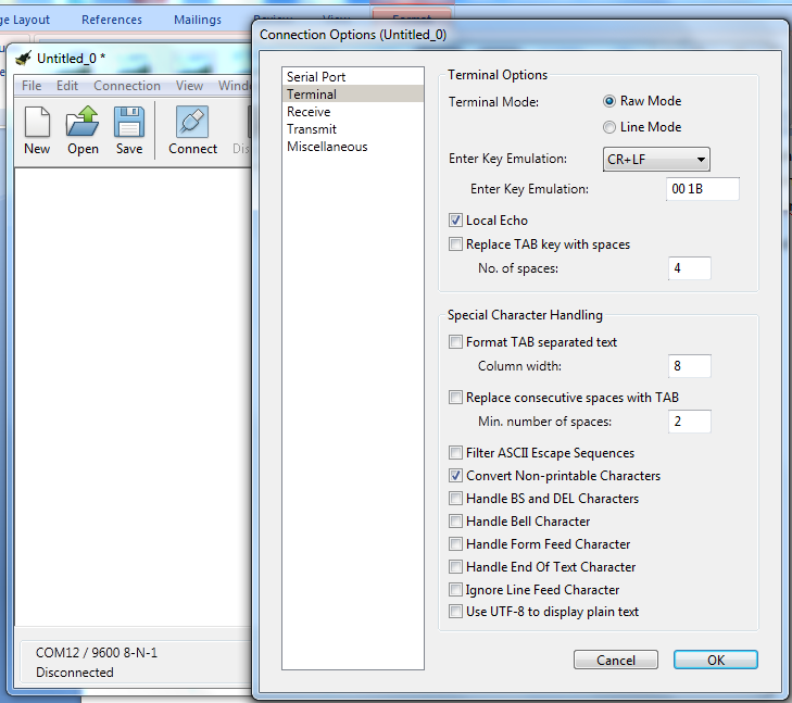
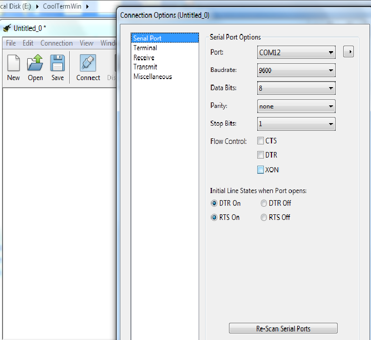
Open the CoolTerm application and navigate to connection -> options -> serial port and select the COM port. Set the baud rate and go to Terminal option and select the Local echo check box to display what typed commands and click OK to save changes.
Screenshot of CoolTerm Application
Fig. 19: Screenshot of CoolTerm Application
Screenshot of Connection Options in Coolterm Application
Fig. 20: Screenshot of Connection Options in Coolterm Application
To configure X-Bee, the following AT commands should be used. 
First make the X-Bee to enter into a command mode by entering +++ in the terminal, once it gets OK then follow with the other AT commands
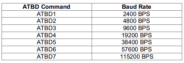
First of all, XBEE radios only operate at a given baud rate, this is the number of bits per second that the X-Bee can send. A brand new X-Bee has default baud rate of 9600 bps, which is quite slow. The baud rate can be changed by altering the ATBD register. Both of the X-Bee modules must have the same baud rate to talk to one another. The available baud rates (and corresponding ATBD value) are as follow –  

Table Listing ATBD Commands for Different Baud Rates

Fig. 21: Table listing ATBD commands for different baud rates
So, to set the baud rate at 9600, the following command should be passed – 
ATBD3
The next important parameter is the Personal Area Network ID. This is a number shared amongst each XBEE in a network. Here, there are only 2 X-Bee modules, but there can be many X-Bee modules in a network (for which Series 2 X-Bee modules should be used). The X-Bee modules on different networks do not “see” each other. The default PAN is 3332, so avoid using that number. The PAN ID is stored in ATID register. The register can be altered by passing the following command – 
ATID1001
Once both of the X-Bee modules are on the same network, each one of them must be given an address number denoted by ATMY register. The destination address can also be set, which is what address number has to talk to and is denoted by ATDL register (for destination low, there is no need to use the high bytes if the address numbers are less than 16 bits in length). A sample setup of two X-Bee modules that will talk directly to one another at 38.4 kbps can be done by passing the following commands – 
ATMY10
ATDL11
So, both X-Bee modules are configured by passing the following AT commands – 
XBEE1:
ATID1001
ATMY10
ATDL11
ATBD3
XBEE2:
ATID1001
ATMY11
ATDL10
ATBD3
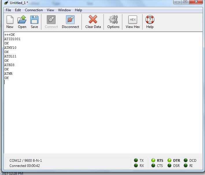
An important thing to note though is that changes made are stored in temporary memory. if X-Bee modules are powered off, the configurations are lost. Send ATWR to write the changes to non-volatile memory, so that they are not lost while power off.
Screenshot of CoolTerm Application showing AT Commands Passed to Xbee Module
Fig. 22: Screenshot of CoolTerm Application showing AT commands passed to Xbee Module
Once the X-Bee modules are configured, the Arduino sketch for the remote circuit and receiver circuit can be uploaded at the respective controller board. 
Check the Arduino Sketch of both side controllers to learn how Arduino boards manage the entire operation in coordination and provide software intelligence to both the remote circuit as well as the control circuitry of the robot. 
Programming Guide – 
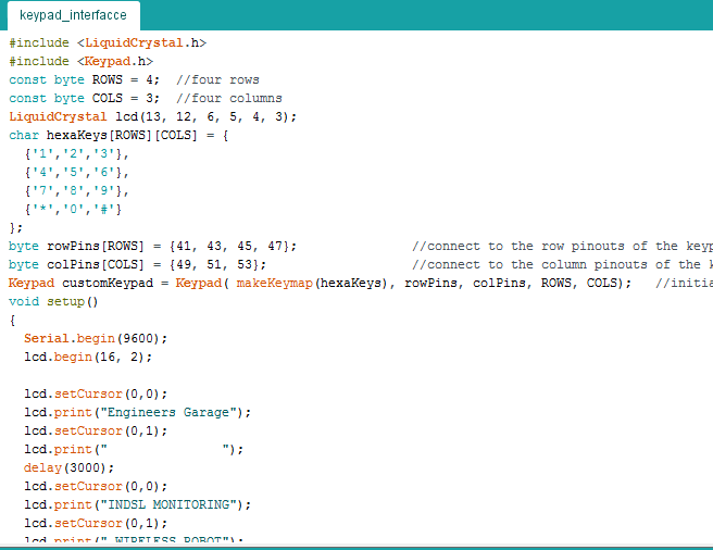
Remote Control Program: The target board for this program is Arduino MEGA. The Arduino code for the remote first of all imports LiquidCrystal.h to handle LCD display and Keypad.h to handle the keypad input. The variables to indicate the number of rows and columns in the matrix keypad are defined and an object of LCD type is instantiated. The keys of the matrix keypad are represented as a multi-dimensional array and a keypad object is instantiated. The setup() function is called in which the baud rate for serial communication with the X-bee module is set to 9600 and LCD is initialized to 16X2 character LCD mode using begin method on the LCD object. Some initial messages are flashed on the LCD display indicating the application of the project.  
Screenshot of Initialization in Arduino Code for Xbee based Gas Monitoring Arduino Robot
Fig. 23: Screenshot of initialization in Arduino Code for Xbee based Gas Monitoring Arduino Robot
The loop() function is called in which the key press is detected using the useKey() method of the Keypad object. The key pressed is stored in a variable and compared with the keys mentioned in the table above using if statements. For each key pressed, a single character string is passed to the X-bee module for transmission using println() function. The functions writes the string character to the serial buffer from which it is transmitted via X-bee module.
Screenshot of Loop Function in Arduino Code for Xbee based Gas Monitoring Arduino Robot
Fig. 24: Screenshot of loop function in Arduino Code for Xbee based Gas Monitoring Arduino Robot
In the loop() function, on pressing the key 1 or 3 it sends the command to measure the concentration of the CO or CO2 gas respectively. The string command used for measurement of CO gas is ‘C’ while the string command used for measurement of CO2 gas is ‘A’. The gas concentration is received as string value from the X-bee module which is converted  to an integer value using atoi() function and is displayed on the LCD screen.
Screenshot of Loop Function in Arduino Code for Xbee based Gas Monitoring Arduino Robot
Fig. 25: Screenshot of loop function in Arduino Code for Xbee based Gas Monitoring Arduino Robot
This completes the Arduino sketch on the remote circuit. Please check out the complete sketch from the code section. 
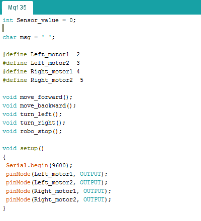
Robot Control Circuit Program: – The target board for this sketch is Arduino UNO. The Arduino code first of all define variables representing the connections of the Arduino pins with the input pins of the motor driver IC. A variable is declared to store the sensor value and a variable is declared to store the message containing the sensor reading. The functions for moving the robot in different directions are declared. This is followed by setup() function which is supposed to run once when the robot is powered on. In the setup() function, the baud rate for serial communication with the X-bee module is set to 9600 and the pins connected to the motor driver IC are configured as digital output using pinMode() function.   
Screenshot of Initialization in Robot Side Arduino Code
Fig. 26: Screenshot of initialization in Robot Side Arduino Code
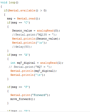
The loop() function is called in which it continuously checks for the incoming serial data, if serial data is available, the data is read using serial.read() function and stored in a variable. Then stored data is checked with the conditions mentioned. Then with respect to the conditions, respective functions are called for moving the robot or measuring the concentration of gas from MQ-7 or MQ-135 sensors.
Screenshot of Loop Function in Robot Side Arduino Code
Fig. 27: Screenshot of loop function in Robot Side Arduino Code
When the command is received to measure the concentration of gas, the values are measured using the analogRead() function and the measured value is sent to the remote circuit in the form of string via X-bee module. When command to move the robot are received, the digital logic at the input pins of the motor driver IC are changed to move the robot in the respective direction. 
This completes the Arduino sketch for the control circuit of the robot. Check out the complete sketch in the code section. 

Project Source Code

###


//Program to
 
#include 

#include 

const byte ROWS = 4;  //four rows

const byte COLS = 3;  //four columns

LiquidCrystal lcd(13, 12, 6, 5, 4, 3);

char hexaKeys[ROWS][COLS] = {

  {'1','2','3'},

  {'4','5','6'},

  {'7','8','9'},

  {'*','0','#'}

};

byte rowPins[ROWS] = {41, 43, 45, 47};               //connect to the row pinouts of the keypad

byte colPins[COLS] = {49, 51, 53};                   //connect to the column pinouts of the keypad

Keypad customKeypad = Keypad( makeKeymap(hexaKeys), rowPins, colPins, ROWS, COLS);   //initialize an instance of class NewKeypad

void setup()

{

  Serial.begin(9600);

  lcd.begin(16, 2);


  lcd.setCursor(0,0); 

  lcd.print("Engineers Garage");

  lcd.setCursor(0,1);

  lcd.print("               "); 

  delay(3000);

  lcd.setCursor(0,0);

  lcd.print("INDSL MONITORING");

  lcd.setCursor(0,1);

  lcd.print(" WIRELESS ROBOT");  

  delay(3000); 

}


void loop()

{

  char customKey = customKeypad.getKey();  


  if(customKey == '2')

  {

        Serial.println("F");

        lcd.clear();

        lcd.setCursor(0, 0);

        lcd.print("<--Direction-->");

        lcd.setCursor(0, 1);

        lcd.print("    FORWARD");

  }


   if(customKey == '8')

  {

        Serial.println("B");

        lcd.clear();

        lcd.setCursor(0, 0);

        lcd.print("<--Direction-->");

        lcd.setCursor(0, 1);

        lcd.print("   BACKWARD");

  }


  if(customKey == '4')

  {

        Serial.print("L");

        lcd.clear();

        lcd.setCursor(0, 0);

        lcd.print("<--Direction-->");

        lcd.setCursor(0, 1);

        lcd.print("     LEFT");

  }


  if(customKey == '6')

  {

        Serial.println("R");

        lcd.clear();

        lcd.setCursor(0, 0);

        lcd.print("<--Direction-->");

        lcd.setCursor(0, 1);

        lcd.print("     RIGHT");

  }


  if(customKey ==  '5')

  {

        Serial.println("S");

        lcd.clear();

        lcd.setCursor(0, 0);

        lcd.print("<--Direction-->");

        lcd.setCursor(0, 1);

        lcd.print("     STOP");

  }     


  if(customKey ==  '1')

  {

        Serial.println("C");

        lcd.clear();

        lcd.setCursor(0, 0);

        lcd.print("  CarbonMonoxide");

        lcd.setCursor(0, 1);

        lcd.print("   Reading"); 

        delay(500);

        char buffer[] = {' ',' ',' ',' ',' '};

        while (!Serial.available());

        //when serial is available read the data till newline and store to buffer

        Serial.readBytesUntil('n', buffer, 10);

        //converting the charcter to integer

        int incomingValue = atoi(buffer);

       // Serial.println(incomingValue);

        lcd.clear();

        lcd.setCursor(0, 0);

        lcd.print("Measured value");

        lcd.setCursor(0, 1);

        lcd.print(incomingValue);

  }     

  if(customKey == '3')

    {

        Serial.println("A");

        lcd.clear();

        lcd.setCursor(0, 0);

        lcd.print("  AirQuality");

        lcd.setCursor(0, 1);

        lcd.print("   Reading");

        delay(500);

        char buffer[] = {' ', ' ', ' '};

        while(!Serial.available());

        Serial.readBytesUntil('n', buffer, 10);

        int incomingValue = atoi(buffer);

        lcd.clear();

        lcd.setCursor(0, 0);

        lcd.print("Measured value");

        lcd.setCursor(0, 1);

        lcd.print(incomingValue);

  }

}

###


Circuit Diagrams

Circuit-Diagram-Remote-Control-Xbee-Gas-Monitoring-Arduino-Robot
Circuit-Diagram-Xbee-Gas-Monitoring-Arduino-Robot

Project Video

Related Articles Read More >

Arduino-based automatic car windows for protection from dust and pollution
Raspberry Pi Server based Hotel/Restaurant Order Management System on IoT – IOT Part 46
Servo Control using Brain Wave (Part 12/13)
Raspberry Pi camera QR-code scanning

Featured Tutorials

  • Remote Controlling Multiple Loads Using RF Module (Part 2/23)
  • Increasing Range of RF Module by Increasing Transmission Power (Part 3/23)
  • Increasing range of RF module by using antenna (Part 4/23)
  • Increasing the Range of RF Module by Using Antenna and Increasing Transmission Power (Part 5/23)
  • Controlling Multiple RF Receivers by Universal RF Transmitter (Part 6/23)
  • Multiple RF Receivers Controlled by a Universal RF transmitter based on Address Pin Configuration (Part 7/23)

Stay Up To Date

Newsletter Signup

EE Training Center Classrooms

“ee

“ee

“ee

“ee

“ee

Recent Articles

  • IAR Systems announces IEC and ISO certifications of its RISC-V development tools
  • Mathematical equations executed by an MCU
  • Infineon’s new Wi-Fi 6 brings reliable connectivity to smart homes
  • Toshiba releases compact LDO regulators for stabilizing DC power lines
  • Clap sensor using STM32 MCU
...

RSS EDABOARD.com Discussions

  • Stumped with buck converter simulation Pspice
  • CMCON0 and ANSEL registers
  • Smart high side switch is a 200mA current clamp device?
  • Finding Difficulty in Selection LED MATRIX
  • MCLR as digital input is resetting the device

RSS Electro-Tech-Online.com Discussions

  • Identify Crystal on Ford Immobilizer antenna board
  • GPU price, lol
  • Diode that only allows continuity at 13.5v?
  • ZVS driver circuit
  • Cutting D-shaped and double flat holes
Engineers Garage
  • Analog IC TIps
  • Connector Tips
  • DesignFast
  • EDABoard Forums
  • EE World Online
  • Electro-Tech-Online Forums
  • Microcontroller Tips
  • Power Electronic Tips
  • Sensor Tips
  • Test and Measurement Tips
  • 5G Technology World
  • About Us
  • Contact Us
  • Advertise

Copyright © 2021 WTWH Media LLC. All Rights Reserved. The material on this site may not be reproduced, distributed, transmitted, cached or otherwise used, except with the prior written permission of WTWH Media
Privacy Policy | Advertising | About Us

Search Engineers Garage

  • Projects and Tutorials
    • Circuit Design
    • Electronic Projects
      • 8051
      • Arduino
      • ARM
      • AVR
      • PIC
      • Raspberry pi
      • STM32
    • Tutorials
    • Components
  • Articles
    • Tech Articles
    • Insight
    • Invention Stories
    • How to
    • What Is
  • News
    • EE Design News
    • DIY Reviews
    • Guest Post
    • Sponsored Content
  • Forums
    • EDABoard.com
    • Electro-Tech-Online
    • EG Forum Archive
  • Digi-Key Store
    • Cables, Wires
    • Connectors, Interconnect
    • Discrete
    • Electromechanical
    • Embedded Computers
    • Enclosures, Hardware, Office
    • Integrated Circuits (ICs)
    • Isolators
    • LED/Optoelectronics
    • Passive
    • Power, Circuit Protection
    • Programmers
    • RF, Wireless
    • Semiconductors
    • Sensors, Transducers
    • Test Products
    • Tools
  • EE Resources
    • DesignFast
    • LEAP Awards
    • Oscilloscope Product Finder
    • Video
    • White Papers
    • Webinars
  • EE Learning Center
  • Women in Engineering