Stepper motor working
I am going to use four steep stepper motor in this project. There are generally 5 or 6 wires coming out of a four steep stepper motor. In 5 wires, one is our vcc(external voltage) and the 4 renaming are step wires. In 6 wired 2 are our vcc(external voltage) and the renaming four are step wires.
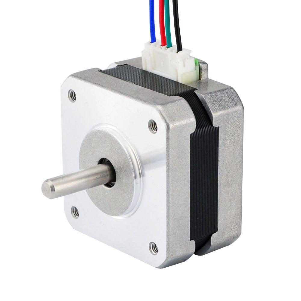
Stepper motor works on 5 volts to 12 volts. Stepper motor which i am using in this tutorial is NEMA 17. Its a bipolar stepper motor. Each step taken by nema 17 stepper motor counts to 1.8 degree increase. So in 200 steps nema 17 complete one rotation 360(200*1.8= 360) degree. Our concern in this tutorial is only to rotate the stepper motor.
Stepper motor power consumption
ULN2003 driver use for stepper motor

8051 microcontroller stepper motor – Project circuit
Connect 8051(89c51) microcontroller Port#1 lower four bits to ULN2003 driver ic. 89c51 microcontroller is unable to output sufficient voltage/current to drive a motor so a driver ic is needed to fullfil motor voltage/current requirements. The output of the ULN2003 is connected to our stepper motor. Make sure to input same wire to motor which you are specifying in your code step. Make pin 8 of ULN2003 ground. Apply same voltage on ULN2003 pin 9 which you are giving to your motor.
Stepper motor interface with 89c51 microcontroller circuit diagram is given below. Note the steps taken by stepper motor in GIF image below. For each step we have to make each step pin high and follow the pattern shown in the GIF image. Stepper motor step pins/wires are colored yellow, brown, black and green etc. We first have to make sure the step wires pattern. Nema 17 stepper motor pattern is shown in the GIF image.
Note: The pattern must be in right order to rotate the stepper motor. Pay attention to the color code of steeper motor wires below.

Stepper motor interface with 8051 microcontroller – Project code
The code is very simple. It is written in c++ language using keil ide as software tool to write and compile the code. First the necessary file reg51.h is included. Then a delay function is created to give some delays in steps. This delay is very important use it to avoid back emf(electric motive force) generated by motor, other wise your controller will be damaged by this back emf produced by stepper motor. You can also speed up the motor rotation by reducing delay time. In the main function i used some commands to rotate stepper motor. The commands are explained below. The commands are in hexadecimal format.
P1=0x01 Making Port 1 bit 0 high for first step. Binary equivalent=00000001
P1=0x00 Making port 1 all bits 0 for next step. Binary equivalent=00000000
P1=0x02 Making port 1 bit 1 high for second step. Binary equivalent=00000010
P1=0x00 Making port 1 all bits 0 for next step. Binary equivalent=00000000
P1=0x04 Making port 1 bit 2 high for third step. Binary equivalent=00000100
P1=0x00 Making port 1 all bits 0 for next step. Binary equivalent=00000000
P1=0x08 Making port 1 bit 3 high for fourth step. Binary equivalent=00001000
You can also individually declare the bits and make them high and low for sufficient steps. The while(1) loop is continuously running the motor in clock wise direction. You can also reverse the direction anticlock wise by just reversing the commands, place the last command(0x08) at first and reverse the
order in same way for rest of the commands.
With a slight modification in code you can vary the speed of stepper motor with 89c51 microcontroller. Just decrease the delay or remove it. To rotate to a certain angle calculate the steps required to reach the angle and place the steps in for loop. I hope it makes sense to you.
More projects involving stepper motors and different microcontrollers are listed below. Each project is unique and a dedicated microcontroller is controlling the stepper motor. All the projects are open source. You can modify them according to your needs.
Watch 89c51 stepper motor interface project video
You may also like:


Filed Under: 8051, Electronic Projects, Featured Contributions

Questions related to this article?
👉Ask and discuss on EDAboard.com and Electro-Tech-Online.com forums.
Tell Us What You Think!!
You must be logged in to post a comment.