Engineers Garage

  • Projects and Tutorials
    • Circuit Design
    • Electronic Projects
      • 8051
      • Arduino
      • ARM
      • AVR
      • PIC
      • Raspberry pi
      • STM32
    • Tutorials
    • Components
  • Articles
    • Tech Articles
    • Insight
    • Invention Stories
    • How to
    • What Is
  • News
    • EE Design News
    • DIY Reviews
    • Guest Post
    • Sponsored Content
  • Forums
    • EDABoard.com
    • Electro-Tech-Online
    • EG Forum Archive
  • Digi-Key Store
    • Cables, Wires
    • Connectors, Interconnect
    • Discrete
    • Electromechanical
    • Embedded Computers
    • Enclosures, Hardware, Office
    • Integrated Circuits (ICs)
    • Isolators
    • LED/Optoelectronics
    • Passive
    • Power, Circuit Protection
    • Programmers
    • RF, Wireless
    • Semiconductors
    • Sensors, Transducers
    • Test Products
    • Tools
  • EE Resources
    • DesignFast
    • LEAP Awards
    • Oscilloscope Product Finder
    • Video
    • White Papers
    • Webinars
  • EE Learning Center
  • Women in Engineering

GLCD 128×64 graphical lcd(GLCD) interfacing with 8051(89c51,89c52) microcontroller

February 10, 2021 By EG Projects

In this tutorial i am going to teach you how to interface graphical lcd 128×64 with 8051(89c51,89c52)microcontroller. 128×64 means that lcd has 128 coulombs and 64 rows. Which means you can make your desired image or text in 128×64 matrix square. Graphical lcds comes in many sizes, they also differ in characteristics. Some can be directly connected to your PC and you just need to learn simple commands to send pictures and text to lcd, these graphical lcds comes with free software with them. Some are just simple lcds and you need to control them with some intelligent unit like microcontroller etc. In this tutorial we are going to control the same simple graphical lcd using 89c51 microcontroller. We will display text on graphical lcd using 8051 microcontroller. 

How graphical lcds work?

I am going to interface jhd12864e graphical lcd with 8051 microcontroller. To learn about full pin description and internal organization of pixels of jhd12864e graphical lcd please go through the simple tutorial. This will lead you to easily understand the code written below.

  • 128×62 Graphical lcd Pin out and Description

The above tutorial is very important to understand the GLCD code below. If yon don’t know about the GLCD working then you can not understand the 8051 microcontroller with GLCD code below. Pin out of GLCD jhd12864e is given below.

JHD128x64 graphical lcd pin out

JHD128x64 graphical lcd pin out

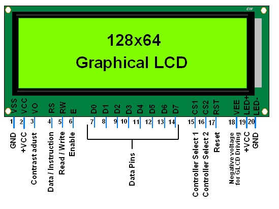
JHD12864e GLCD with 8051 microcontroller

I am going to print my website name “microcontroller-project.com” on glcd. First i decided text font to display on GLCD. II finalized the character height to 8 rows and 5 to 6 coulombs in width. You can display text according to your desire. Since you have lot of available space from 128 coulombs to 64 rows. Combine pages to make font greater and greater(If you don’t know what is page in graphical lcd please go through the upper tutorial).

Steps to display text on GLCD

  • Initialize the jhd12864e glcd(Display on-off,set x,y address,set start line)  
  • Select the graphical lcd half(left or right)                      Don’t understand! Take the Upper tutorial.
  • Select the page                                                             Don’t understand! Take the Upper tutorial.
  • Make and display text                                                   Don’t understand! Take the Upper tutorial.

How text is made and displayed on GLCD?

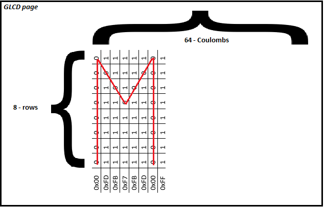
Now when you are done with initializing glcd and selected glcd half and page. Its time to make/display text or image on glcd. Each page of GLCD is organized in rows and coulombs (8×64 in dimension) 8 rows and 64 coulombs. Each coulomb in a page has 8 dots aligned vertically. We send an eight bit data to make these dots ON or OFF. 0 is OFF and 1 is ON. A simple command like FF=11111111 makes all dots of coulomb ON & F0=11110000 makes first four dots OFF and last four ON. You make your desired text or image by making these pixels ON or OFF. The combination of all coulombs makes a picture. 

For example to display the ‘M‘ character on Glcd the data send to GLCD is below. Data is send to glcd 8-bit at a time. 8-bit data is in hexadecimal format. If we translate hexadecimal to binary it will represent the below character. Last command is not displaying any thing. Its actually the gap for another character to appear a head of ‘M‘.

Making and displaying character on page of GLCD

Making and displaying character on page of GLCD

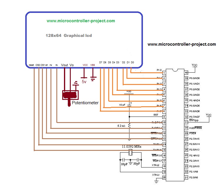
JHD12864e interfacing with 8051 microcontroller – Project circuit diagram

Circuit diagram of the project is simple. Connect Port-1 of 8051(89c51,89c52) microcontroller with data pins of graphical lcd. Port-3 pin 0 is connected to rs(register select) pin of graphical lcd. Port-3 pin 1 is connected to rw(read-write pin of graphical lcd). Port-3 pin 2 is connected to en(enable) pin of lcd. Port-3 pin 3 and 4 are connected to cs1(chip select 1) and cs2(chip select 2) to 128×64 graphical lcd. Port-3 pin 5 is connected to reset pin of 128×64 graphical lcd. Rest of the connections are for 8051 microcontroller initialization. Circuit diagram of the project is below.

Graphical lcd with 8051(89c51,89c52)

Graphical lcd with 8051(89c51,89c52) circuit diagram

GLCD interface with 89c51 microcontroller code

Coming to code of GLCD project. it is written in c language using keil uvision 3 software to compile and create hex code. First the header file reg51.h is included(it is to be included in every project made in keil for 8051 microcontroller). Then single bits of Port-3 are defined. These pins are used to control jhd12864e graphical lcd. delay() function is generating some delay for us to be used where necessary. lcdcmd() function is sending commands to glcd. lcddata() function is sending data to glcd. The main function is controlling all the displaying and control functions. Each command is commended with its function.

While(1) loop at the end only runs the code once. Website name “microcontroller-project.com” will be displayed on two pages of jhd12864e.  

Note: Some graphical lcds select cs1, cs2(chip select) on 1 and some with 0. If you are using this code be sure that 0 selects your cs1 & cs2. If not 0 then switch cs1 & cs2 in the code just make cs1=1 where it is 0 and cs2=0 where it is 1.

Some more microcontroller projects involving jhd12864e graphical lcd are below. Images are also displayed on GLCD using variety of microcontrollers.

  • Graphical Lcd JHD12864E with Pic Microcontroller
  • Displaying Images On Graphical Lcd 128×64
Download the project files. Folder includes project code(Hex,c++) and simulation. Code is written in c language and keil uvision 3 is used to compile code. Simulation is made in proteus 8. If you have any quextions plz write them below.
                                                                                                                                                                                     Graphical lcd with 8051 files/code

Related Articles Read More >

Remote Controlling Multiple Loads Using RF Module (Part 2/23)
Increasing Range of RF Module by Increasing Transmission Power (Part 3/23)
Increasing range of RF module by using antenna (Part 4/23)
Increasing the Range of RF Module by Using Antenna and Increasing Transmission Power (Part 5/23)

Featured Tutorials

  • Remote Controlling Multiple Loads Using RF Module (Part 2/23)
  • Increasing Range of RF Module by Increasing Transmission Power (Part 3/23)
  • Increasing range of RF module by using antenna (Part 4/23)
  • Increasing the Range of RF Module by Using Antenna and Increasing Transmission Power (Part 5/23)
  • Controlling Multiple RF Receivers by Universal RF Transmitter (Part 6/23)
  • Multiple RF Receivers Controlled by a Universal RF transmitter based on Address Pin Configuration (Part 7/23)

Stay Up To Date

Newsletter Signup

EE Training Center Classrooms

“ee

“ee

“ee

“ee

“ee

Recent Articles

  • IAR Systems announces IEC and ISO certifications of its RISC-V development tools
  • Mathematical equations executed by an MCU
  • Infineon’s new Wi-Fi 6 brings reliable connectivity to smart homes
  • Toshiba releases compact LDO regulators for stabilizing DC power lines
  • Clap sensor using STM32 MCU
...

RSS EDABOARD.com Discussions

  • How can I explan this simple PWM creator Circuit
  • Can I use a Virtual clock instead of using a create_clock?
  • MCLR as digital input is resetting the device
  • Symmetrical Fully Differential Amplifier Layout
  • What is the DC voltage rating of this Y2 capacitor?

RSS Electro-Tech-Online.com Discussions

  • NTC flakey
  • Diode that only allows continuity at 13.5v?
  • Can two N-Channel MOSFETs be connected in series to perform a "AND" function?
  • Cycle Indicator Lights
  • #MEASURING OUTPUT VOLTAGE# Ideal laboratory power supply - YOURS requirements
Engineers Garage
  • Analog IC TIps
  • Connector Tips
  • DesignFast
  • EDABoard Forums
  • EE World Online
  • Electro-Tech-Online Forums
  • Microcontroller Tips
  • Power Electronic Tips
  • Sensor Tips
  • Test and Measurement Tips
  • 5G Technology World
  • About Us
  • Contact Us
  • Advertise

Copyright © 2021 WTWH Media LLC. All Rights Reserved. The material on this site may not be reproduced, distributed, transmitted, cached or otherwise used, except with the prior written permission of WTWH Media
Privacy Policy | Advertising | About Us

Search Engineers Garage

  • Projects and Tutorials
    • Circuit Design
    • Electronic Projects
      • 8051
      • Arduino
      • ARM
      • AVR
      • PIC
      • Raspberry pi
      • STM32
    • Tutorials
    • Components
  • Articles
    • Tech Articles
    • Insight
    • Invention Stories
    • How to
    • What Is
  • News
    • EE Design News
    • DIY Reviews
    • Guest Post
    • Sponsored Content
  • Forums
    • EDABoard.com
    • Electro-Tech-Online
    • EG Forum Archive
  • Digi-Key Store
    • Cables, Wires
    • Connectors, Interconnect
    • Discrete
    • Electromechanical
    • Embedded Computers
    • Enclosures, Hardware, Office
    • Integrated Circuits (ICs)
    • Isolators
    • LED/Optoelectronics
    • Passive
    • Power, Circuit Protection
    • Programmers
    • RF, Wireless
    • Semiconductors
    • Sensors, Transducers
    • Test Products
    • Tools
  • EE Resources
    • DesignFast
    • LEAP Awards
    • Oscilloscope Product Finder
    • Video
    • White Papers
    • Webinars
  • EE Learning Center
  • Women in Engineering