There are generally six power modes in an MCU:
- Run: In full run mode, an MCU consumes full current. This mode is best suited for applications where power efficiency is not essential.
- Doze: As we know, power increases proportionally to the frequency. Therefore, we can conclude that higher clock speeds tend to higher power consumption. Doze mode helps to reduce power consumption. In Doze mode, the CPU and Flash memory runs at a lower clock rate than the rest of the chip as Flash and CPU are very power-hungry components.
- Idle: In idle mode, the CPU and Flash stop, and the rest of the chip continues to operate.
- Sleep: In sleep mode, we can save more than 90% of the power consumed in Run. Typically, MCUs achieve the lowest power consumption in sleep mode, consuming nano amps or microamps of current. The CPU, Flash, and most peripherals are disabled or offline in this mode. Some peripherals are available, like the A/D, UART Interrupt, and some timers, which allow the MCU to accomplish some work in the system, waking it up at a specific time.
- Low Voltage Sleep: In this mode, a second regulator can be employed to reduce the voltage to the logic gates. This significantly reduces the leakage current of the MCU.
- Deep Sleep: In this mode, the CPU, flash, RAM, and nearly all peripherals are disabled. Only low-power peripherals, such as the Real-Time Clock, Deep Sleep Brown-out for detecting battery droop, a watchdog timer, and the ultra-low-power wake-up feature, remain powered. With power removed from most of the chip, the current consumption can be as low as 20nA.
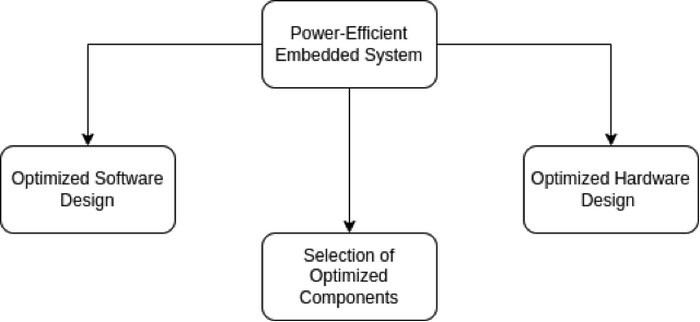
In this series, we will present three experiments to better understand the low power mode.
Experiment 1
Aim
To run an MCU on low power mode, read the temperature and humidity reading using the AHT10 sensor, and send the reading over WiFi.
Requirements
- MCU: ESP32-WROOM-32D (generic Wi-Fi + Bluetooth + Bluetooth LE MCU module)
- Sensor: AHT10 (temperature and humidity sensor)
- Battery: AA battery MX1500 (3.6V, 2700mAh)
Theory
In this experiment, we are using the MCU ESP32-WROOM-32D. Here we will learn how to use a timer to wake up the ESP32. The ESP32 will remain in the active mode for 2-3 seconds, take the temperature and humidity reading, and send it over WiFi. After that, the ESP32 will be back in deep sleep mode. It will remain in deepsleep() mode for five minutes.
ESP32 power modes
The ESP32 chip has mainly two types of processors, the main and the ultra-low power, or ULP processor. ESP32 usually consumes about 75mA current in normal operation and about 240mA while transmitting data over WiFi. ESP32 deep sleep mode will reduce the power consumption and increase the battery life as every mA is critical with a battery. Five configurable power modes manage ESP32’s current consumption.
- Active
- Modem Sleep
- Light Sleep
- Deep Sleep
- Hibernation
The table below details the power modes:
In the deep sleep mode, the RTC (real-time clock) controller, peripherals, and memories are in active mode. Most of the RAM with all the digital peripherals and the CPU is powered off in deep sleep mode. Only the RTC module is active, which results in the data loss not initially present in the RTC recovery memory. If the ULP co-processor is turned on, the current consumption goes low to 0.15 mA – 10 µA. Note that the system cannot go into deep sleep mode automatically.
The function that can be used to activate the deep sleep once wake-up sources are configured immediately is:
“esp_deep_sleep_start()”
ESP32 wake up sources
There are several ways to wake up the ESP board from deep sleep mode.
- Timer, wake up. Waking up your ESP32 using predefined periods of time, which is achieved through the function: “(esp_sleep_enable_timer_wakeup(sleep_time_in_us)”
- Touch pin wake-up. We can wake up the ESP32 from deep sleep using the touch pins achieved using the following function:
“esp_sleep_enable_touchpad_wakeup()”
- External wake-up. We can wake up the ESP32 using multiple RTC GPIOs. There are two different logic functions.
Wake up the ESP32 if any of the selected pins are high.
Wake up the ESP32 if all the pins you’ve selected are low.
We need to use the following function:
“esp_sleep_enable_ext1_wakeup(bitmask, mode)”
Schematic
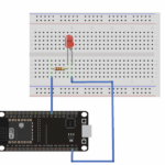
In this schematic, you may recognize functions we studied in earlier articles to reduce power consumption. We run the circuit on a low power supply (3V). The value for the resistor with the LED is of high value(1K), and the pull up for Enable pin is also of high value (20K). We have not used the pull-ups for the I2C connection because we will use the internal pull-ups of the ESP32 instead.
 Experiment setup
Below is the image showing the setup of the experiment.
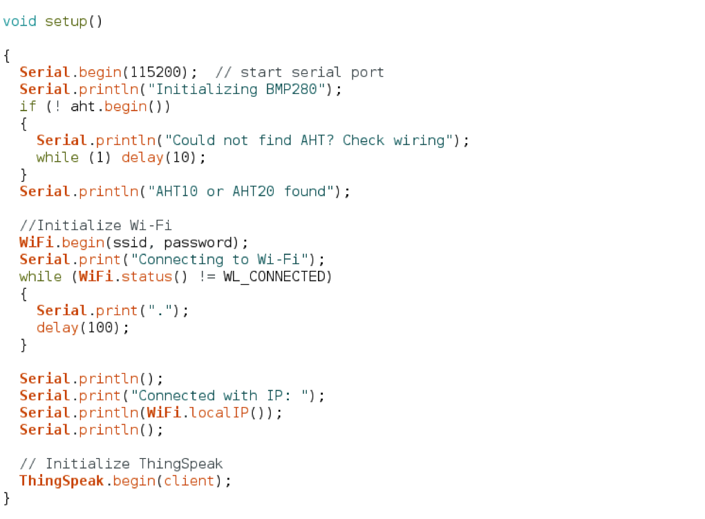
Code
Observation table
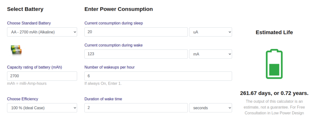
- The Current Consumption by the ESP32 in active mode is ~123 mA.
- The battery capacity is 2700 mAH.
- According to the battery’s datasheet, its shelf life is about seven years.
- The monthly self-discharge rate of the AA alkaline battery is 0.3 %.
Battery Capacity(mAH) * Self Discharge Rate / 100 = Self-Discharge Current (mAH)
2700 mAH * 0.3 / 100 = 8.1 mAH
This means that a 2700 mAH battery will self-discharge 3% losses or 8.1 mAH of its capacity after one month.
Shelf Life = 2700 mAH /( 8.1 mAH) = 333.3 months = ~ 27 Years
- Battery life calculation,
Results
Below are the results of the device’s data sent to the ThinkSpeak Platform.

Fig: 6 Readings of Temperature from AHT10 sensor (left). Readings of Humidity from AHT10 sensor (right)
According to the above, the battery with 2700mAH capacity will have a life of approximately 261 days if the current drawn from the battery is 123mA during active mode.
You may also like:
Filed Under: PIC Microcontroller., Power, Tech Articles, Tutorials






Questions related to this article?
👉Ask and discuss on Electro-Tech-Online.com and EDAboard.com forums.
Tell Us What You Think!!
You must be logged in to post a comment.