In the previous tutorial, Analog I/O Line Passing between two X-Bee modules was done. In this tutorial, X-Bee modules will be used to read and transmit digital data. The X-Bee modules are often used with the microcontrollers which may pass data to the module as digital data. Even the module itself is capable of sensing digital data from sensors and switches as it has 8 digital input/output pins. For reading or writing digital data, these pins or any of these pins can be configured to read or write operation.
Components Required –
1) X-Bee Modules – 2
2) Arduino UNO
3) Breadboards
4) Connecting Wires
5) FTDI USB to Serial converter cable
6) PC
7) switch
Circuit Connections –
In this project, two X bee series 1 (S1) modules are used. One module serves as Transmitter and the another one as Receiver. Both the modules will be connected PCs for passing AT commands and monitoring Data transfer. A X-Bee module is a 20-pin module with the following pin configuration –

For connecting a Zig-Bee module with PC, FTDI USB to Serial converter cable can be used. The convertor cable has four pins – VCC, Ground, RX and TX. These pins should be connected to the X-Bee module in the following manner –

Another way of connecting the X-Bee module with PC is connecting it via Arduino board. The PC and Arduino board can be connected by an USB cable. The RX and TX pin of the Arduino can be connected to the Tx and RX pins of the Zig-Bee module and Reset pin of the Arduino UNO can be grounded. Now by loading the ‘Bare Minimum’ Arduino Sketch on the board, it can be used for serial communication with the X-Bee module.
Both the modules need to be powered by 3.3 V batteries. according to the pin configuration of the X-Bee modules, the positive terminal of the battery should be connected at pin 1 of the module and negative terminal to the pin 10 of the module.
The X-Bee module to be used as transmitter will be fed digital input through a switch connected at pin 20 of the module. The pin 20 of X-Bee is Analog Input 0 as well as Digital I/O 0. It needs to configured as digital input by passing appropriate AT commands. The pin 20 will be by default connected to ground, so the default logic read by the pin will be LOW. On pressing the switch, the pin will short circuit to VCC, therefore reading a HIGH logic. So the switch will be connected at pin 20 in pull down configuration.
The X-Bee module to be used as receiver will have an LED connected at pin 20 of the module. At the receiver module, pin 20 will be configured as digital output instead of digital input.
How the circuit works –
The AT commands will be used to configure both the module. The transmitter module will be configured to read digital data and pair with receiver module to pass the data to it. The commands will be transferred using ‘CoolTerm’ application by the PC. At the transmitter module following configuration parameters will be required to be changed –
1) PAN ID
2) Destination Low Address
3) Source Address
4) Data I/O pin 0 (20th pin)
5) I/O sampling rate
These parameters will be set to the following values using the AT commands –
1) PAN ID = 3332
2) Destination Low Address = 0x22
3) Source Address = 0x24
4) Data I/O pin = 0x03 (Passing 0x03 configures the pin to Digital Input)
5) I/O Sampling rate = 0x1E (30sec)
The following AT commands are passed for changing the configuration parameters for the transmitter module –
The receiver module will be configured to pair with the transmitter module and output digital data at pin 20 according to the passed data from the other module. At the receiver module following configuration parameters will be required to be changed –
1) PAN ID
2) Destination Low Address
3) Source Address
4) Data I/O pin 0 (20th pin)
5) Set ATIA
These parameters will be set to the following values using the AT commands –
1) PAN ID = 0x3332 (Setting the PAN ID same as transmitter Address pairs the two modules)
2) Destination Low Address = 0x24 (Receiver’s DL Address should be same as Transmitter Source address)
3) Source Address = 0x22 (Transmitter Destination Low address should be same as the Receiver’s Source address)
4) Data I/O pin = 0x04 ( Passing 0x04 configures the pin to digital output)
5) Set “ATIA” as Source address of the transmitter (24) so that pin 20 of the receiver follows the changes at pin 20 of the transmitter.
ATIA is Address command. It helps in enabling the pin output mode updates from the other X-Bee Radio.
The following AT commands are passed for changing the configuration parameters for the receiver module –
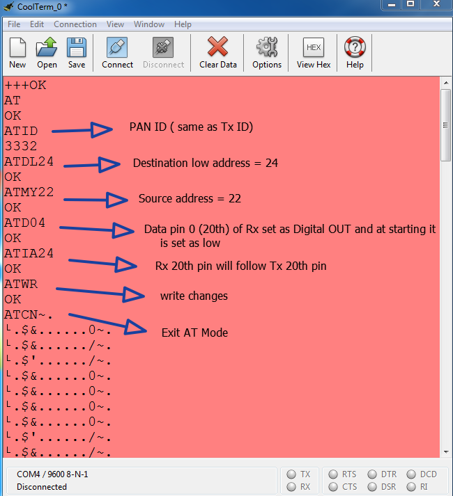
After configuring each module, the settings must be saved by sending ATWR Command and finally exit from the AT mode by using ‘ATCN’ command. After configuring the modules and saving the configurations, if the switch on transmitter module is pressed, the LED connected at receiver module starts glowing and as the switch is released, the LED at the receiver module also gets turned OFF.

Not only a single pin but all the digital input/output pins can be configured on X-Bee modules for transferring digital data.
You may also like:


Project Source Code
Project Source Code
###
//Program to###
Filed Under: Tutorials

Questions related to this article?
👉Ask and discuss on EDAboard.com and Electro-Tech-Online.com forums.
Tell Us What You Think!!
You must be logged in to post a comment.