A battery-management system (BMS) is an electronic system or circuit that monitors the charging, discharging, temperature, and other factors influencing the state of a battery or battery pack, with an overall goal of accurately indicating the remaining time available for use. It’s used to monitor and maintain the health and capacity of a battery.
Today’s BMS devices are advanced and often provide pop-up notifications, as you’ve likely experienced on a laptop or smartphone. At a minimum, these systems should provide:
- Voltage monitoring (state of charge)
- Battery life and overall health (state of health)
- Temperature and condition monitoring (safe operating area)
- Charging time
A battery-management system might also offer additional features, depending on the application. For example, a BTS display in electric vehicles can report how many miles or kilometers the vehicle can safely run before the next charge.
In this article, we’ll learn how a battery management system works, including how it calculates and monitors battery life.
Understanding a BMS
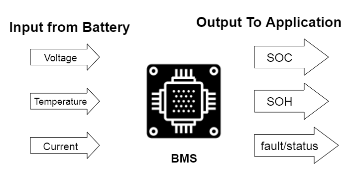
Typically, a BMS receives input from the battery it’s monitoring, processes it in an algorithm, and then generates the output. The output data includes the state of change (SOC), the state of health (SOH), as well as a fault and status signal.
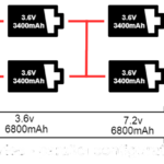
A BMS can be used for a single or multi-cell battery pack. The circuit below shows three cells connected in series, where the BMS measures the overall voltage, as well as the voltage of each cell. It also monitors the current via a shunt current or Hall effect sensor.
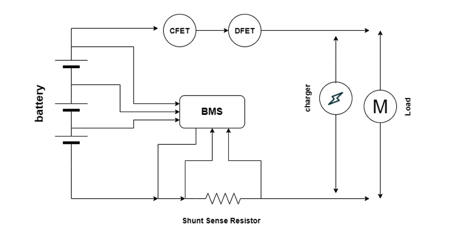
There are also metal–oxide semiconductor field-effect transistors (MOSFETs) available, such as charge or discharge-control field-effect transmitters (CFETs and DFETs), which provide integrated charging and discharging capabilities. These MOSFETs provide an added safety advantage, terminating a charge or loads during a faulty condition. In this case, the charger and the load are connected to “communicate.”
Safe operating area
A BMS provides for safe and reliable battery use. For instance, it can protect a battery from over or under-temperature conditions and over-charge or over-discharge.
The operating temperature and voltage should always be in a safe operating area (SOA), which is indicated in the voltage versus temperature graph below. The value in the graph such as this should always follow the BMS manufacturer’s data sheet as different systems are available.

This is an over-temperature condition if the battery’s temperature exceeds the SOA due to excessively warm or hot conditions. It is considered hazardous as it can melt the cells and circuits. A plastic battery case typically softens at around 200 F and melts above 300 F. In extreme cases, the battery can also melt or explode.
Much like heat speeds up chemical reactions, cold temperatures slow them down. An under-temperature condition can be caused by cold or freezing temperatures, which can also affect the battery and its ability to provide power.
A voltage exceeding its ideal state limits and rising above the SOA is an overcharge, damaging the battery and leaving it functionless. When the voltage drops below its state limit, it’s considered an under-charge. All four conditions can damage the battery or may be dangerous.
A reliable BMS monitors each cell in the circuit and offers protection by terminating the battery’s charge if it surpasses any of the ideal states.
State of health
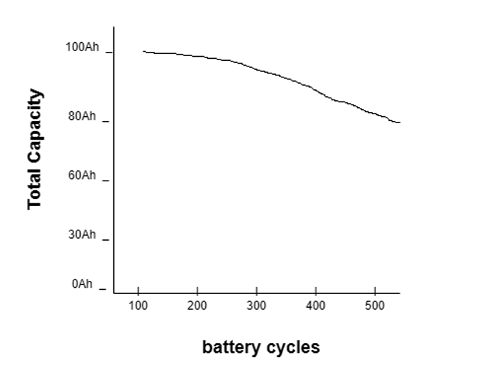
The state of health (SOH) refers to a battery’s capacity or current condition compared to its ideal state. SOH helps to determine the percent of battery life available or remaining.
In the below graph, the battery’s capacity decreases over the charging or discharging cycle.
How is the SOH determined?
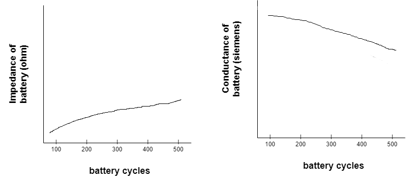
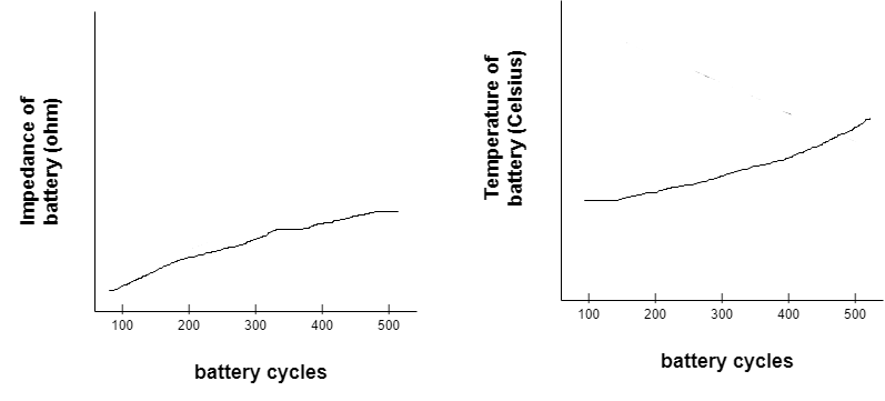
The parameters that change with the age of a battery — such as impedance or conductance — can be used to determine the SOH of a cell. When such parameters increase, battery performance decreases while its temperature increases. Impedance measures a circuit’s opposition to a current when a voltage is applied. Conductance is the degree to which an object conducts electricity, calculated as the current ratio.
To measure the SOH, it’s necessary to record the initial impedance or conductance, which is typically provided on the manufacturer’s datasheet. To test the impedance or conductance of a battery, apply a small AC voltage of “E” known frequency and amplitude across the cell and measure the in-phase AC current “I” that flows in response to it.
Where…
Impedance is Z = E/I (“E” is the AC voltage across the cell, and “I” is the AC current flowing through the battery)
Conductance is C = I/E
For example…
E = 0.0024 V and I = 0.0033 A Z = 0.0024 / 0.0033 = 0.072 ohm
The impedance and conductance are inverse to one another, where the impedance increases and the conductance decreases.
Now, let’s suppose we received an impedance measuring 70 milliohms, but, at first, it was 50 milliohm.
Impedance percentage =(current impedance / initial impedance) X 100
= (70/50) x 100
= 140%
Impedance percentage of increase = impedance percentage – 100
= 140 – 100 = 40%
The impedance has increased by 40 percent. Now, let’s calculate the SOH.
The battery has an initial capacity of 1000mAh, and the impedance increased by 40 percent. As a result…
Capacity lost = (impedance percent /100) x Total initial capacity
= (40/100) x 1000 = 400mAh
SOH = Total initial capacity – capacity lost
= 600mAh
The impedance percentage can also measure the temperature. Let’s say the initial percentage is 40 C.
Current temperature = (impedance percent /100) x initial temperature + initial temperature
= (40/100) x 40 + 40
= 56 C
In this case, as the impedance increases, the battery’s temperature increases, as shown in the graph below.
State of charge
The state of charge (SOC) indicates how much power or energy is left in the battery and is calculated using the remaining battery capacity over the battery’s total capacity. The state of charge can be indicated in the percentage as follows;
SOC percentage = ( SOH / total capacity ) X 100
Although this formula provides the SOC as a percentage, it’s not entirely accurate because it fails to factor in the fact that the battery’s total capacity decreases over time. Eventually, the battery will not achieve a full, 100% charge. The total capacity in the formula, therefore, is the SOH value.
This equation offers a more accurate result:
SOC percentage = ( SOC / SOH ) X 100
If the initial battery capacity is 1000mAh, but the SOH is now 500mAh, and the remaining capacity is 300mAh, then:
SOC percentage = ( 300 / 500) X 100 = 60%
How is the SOC determined?
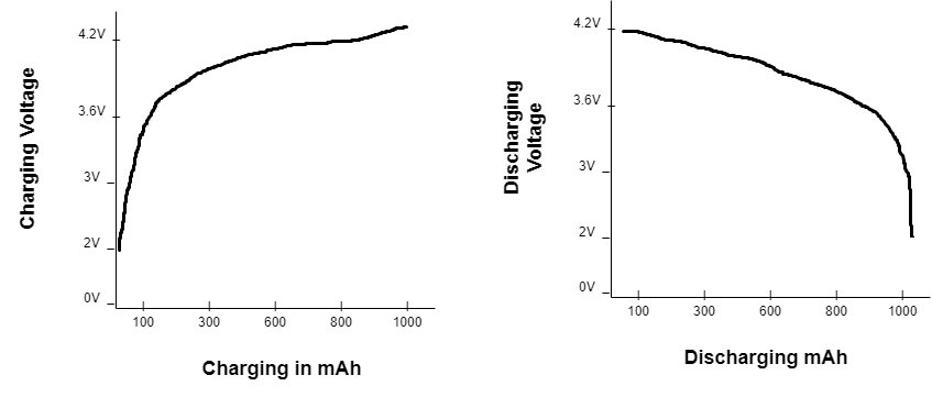
The easiest way to determine the state of charge is by measuring the battery’s charging and discharging voltage. However, this is not the ideal way to measure the capacity because the battery does not have a linear charging or discharging curve. So, not every reading would be accurately represented.
Consider, for example, a lithium-ion battery’s charging and discharging curve in the graphs below. The charging and discharging voltage gradually change the battery state until the final discharge remains stable.
The ideal method for measuring the battery’s capacity is via Coulomb Counting, which measures the incoming and outgoing currents over time. It accounts for the discharge current over time and subtracts it from the values if the charging current is the same.
SOC = Total capacity – (Discharge current – Charged current)
Several methods are available to measure the discharge or a charge in current, depending on the battery-measurement system. Here are a few:
Current shunt: A shunt is a low-ohm resistor used to measure current and, typically, when the current exceeds the range of the measuring device. The entire current flows through the shunt and generates a voltage drop, which is measured. This method has a slight power loss across the resistor and heats the battery.
Hall effect: This sensor measures the changing voltage when the device is placed in a magnetic field. It eliminates the power loss problem typical of the current shunt, but it’s costly and unable to tolerate high currents.
Giant magnetoresistance (GMR): These sensors are used as magnetic-field detectors that are more sensitive (and more expensive) than Hall-effect sensors. They’re incredibly accurate.
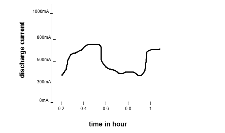
Coulomb counting: Coulomb involves measuring the amount of current flowing into or out of the battery. Below is a graph depicting a current measured at different times to determine the total discharge current concerning time.
The Coulomb measurement is quite complicated but can be done by a microcontroller.
You may also like:

Filed Under: Batteries, Battery Management, Tutorials

Questions related to this article?
👉Ask and discuss on EDAboard.com and Electro-Tech-Online.com forums.
Tell Us What You Think!!
You must be logged in to post a comment.