Engineers Garage

  • Projects and Tutorials
    • Electronic Projects
      • 8051
      • Arduino
      • ARM
      • AVR
      • PIC
      • Raspberry pi
      • STM32
    • Tutorials
    • Circuit Design
    • Project Videos
    • Components
  • Articles
    • Tech Articles
    • Insight
    • Invention Stories
    • How to
    • What Is
  • News
    • Electronic Products News
    • DIY Reviews
    • Guest Post
  • Forums
    • EDABoard.com
    • Electro-Tech-Online
    • EG Forum Archive
  • Digi-Key Store
    • Cables, Wires
    • Connectors, Interconnect
    • Discrete
    • Electromechanical
    • Embedded Computers
    • Enclosures, Hardware, Office
    • Integrated Circuits (ICs)
    • Isolators
    • LED/Optoelectronics
    • Passive
    • Power, Circuit Protection
    • Programmers
    • RF, Wireless
    • Semiconductors
    • Sensors, Transducers
    • Test Products
    • Tools
  • EE Resources
    • DesignFast
    • LEAP Awards
    • Oscilloscope Product Finder
    • White Papers
    • Webinars
  • EE Learning Center
  • Women in Engineering

How to configure Watchdog Timers of AVR Microcontroller (ATmega16)- (Part 15/46)

By Ashutosh Bhatt

Some high end applications require multiple or critical calculations to be done by the microcontroller. This may lead to cases when the controller enters into wrong or infinite loops. As a result of this, the system either hangs up or gets crashed. The solution to overcome these situations is to automatically reset the system whenever such a situation arises.
 
The Watchdog Timer is a hardware or software generated timer interrupt which reboots/resets the system in the situations mentioned above. The watchdog timers are also used in cases when you intentionally require resetting the system without any physical interference.
The AVR microcontroller has an in-built watchdog timer. This article explains the working of watchdog timer in ATmega16.


The Watchdog Timer is a special timer which can be enabled in any section of the code and when enabled it ensures that a certain number of instructions execute within a pre-defined time frame. This time frame or the time delay can be configured/set using the registers of the watchdog timer. In case the instructions execute within the time frame, watchdog timer needs to be turned off and the program execution continues. However, if the instructions fail to execute within this time frame (this conditions is called time out condition) the entire system reboots thus avoiding any system crash or hang up.
 
Watchdog Timer in ATmega16:
The Watchdog timer of Atmega16 can be configured by using WDTCR register of AVR microcontroller. When the time out condition is set, the watchdog timer starts counting clock cycles. The watchdog’s timer is clocked from separate on-chip watchdog oscillator of 1MHz frequency. The time out condition is set by configuring prescaler bits of WDTCR register.
 
WDTCR (Watch Dog Timer Control Register): 
–
–
–
WDTOE
WDE
WDP2
WDP1
WDP0
Bit 7
Bit 6
Bit 5
Bit 4
Bit 3
Bit 2
Bit 1
Bit 0
   Fig. 2: Bit configuration of WDTCR in AVR
 
WDTOE (Watch Dog Turn-Off Enable) – The watchdog timer is disabled by configuring WDTOE and WDE bits (explained later in the article).
 
WDE (Watch Dog Enable) – Watchdog timer is enabled by writing 1 to WDE bit.
 
WDP [2:0] (Watch Dog Prescaler) bits – These three bits determine the watchdog time out condition. The table below shows prescaler bits combination and their corresponding time out period:
 
WDP2
WDP1
WDP0
Number of WDT oscillator cycles
Typical Time-out at Vcc=3.0V
Typical Time-out at Vcc=5.0V
0
0
0
16K (16,384)
17.1 ms
16.3 ms
0
0
1
32K (32,768)
34.3 ms
32.5 ms
0
1
0
64K (65,536)
68.5 ms
65 ms
0
1
1
128K (131,072)
0.14 s
0.13 s
1
0
0
256K (262,144)
0.27 s
0.26 s
1
0
1
512K (524,288)
0.55 s
0.52 s
1
1
0
1024K (1,048,576)
1.1 s
1.0 s
1
1
1
2048K (2,097,152)
2.2 s
2.1 s
   Fig. 3: Watch Dog Prescaler bits combination and time out period
 
How Watchdog Timer works:
The watchdog timer starts when the WDE bit is enabled and prescaler bits are configured for time-out condition. As watchdog timer reaches time-out condition, watchdog timer is reset and generates a pulse of one clock cycle which resets the program counter. When watch dog timer resets the timer, the WDRF (Watch Dog Reset Flag) bit in MCUCSR register is set by the hardware. To disable the watchdog timer following steps must be followed:
1. Set the WDE and WDTOE bits in same clock cycle WDTCR register. The logic one must be written to WDE bit even though it is set to one already.
2. After four clock pulses, write logic 0 to the WDE bit. Otherwise watchdog timer will not be disabled.
 
Objective:
To set watchdog timer condition at 2 seconds (approx.) and check the reset condition.
 
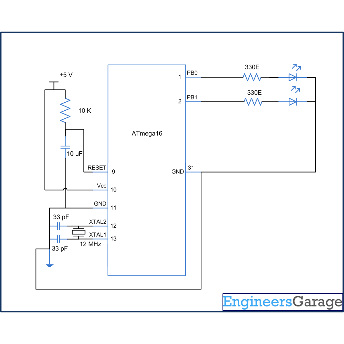
Circuit diagram:
The connection for above mentioned objective is shown in circuit diagram. An LED is connected at pin PB0 which blinks continuously. Another LED is connected to PB1 pin. This LED will glow when watchdog time out condition occurs.
 
Programming steps:
1. Check the status of WDRF bit. If this bit is high, set the PB1 pin of the controller.
2. Set the WDE bit in WDTCR register to activate the watchdog timer.
3. Set the prescaler bits WDP [2:0] = 111 for the time-out condition of 2 sec.
4. Write an infinite loop to toggle the PB0 bits toggles with a certain delay.
5. On time-out condition, watchdog timer resets the controller and this event reinitialize the program counter to go back at step 1.
 

Project Source Code

###


// Program to configure watchdog timer in ATmega16 Microcontroller 
#include<avr/io.h>
#include<util/delay.h>
 
int main()
{
DDRB=0x03;
 
if(bit_is_set(MCUCSR,WDRF))
{
PORTB|=(1<<PB1);
_delay_ms(1000);
}
 
PORTB&=~(1<<PB1);
WDTCR=0x0F;
while(1)
{
PORTB|=(1<<PB0);
_delay_ms(400);
PORTB&=~(1<<PB0);
_delay_ms(400);
}
}

###


Circuit Diagrams

Circuit-Diagram-of-How-to-configure-Watchdog-Timers-of-AVR-Microcontroller-ATmega16

Project Components

  • ATmega16
  • LED

Project Video


Filed Under: AVR Microcontroller
Tagged With: atmega16, avr, microcontroller, timer, watchdog timer
 

Questions related to this article?
👉Ask and discuss on Electro-Tech-Online.com and EDAboard.com forums.


Tell Us What You Think!! Cancel reply

You must be logged in to post a comment.

HAVE A QUESTION?

Have a technical question about an article or other engineering questions? Check out our engineering forums EDABoard.com and Electro-Tech-Online.com where you can get those questions asked and answered by your peers!


Featured Tutorials

  • Designing Gate Driver Circuit and Switching Mechanism for Modified Sine Wave Inverter – (Part 9/17)
  • Completing Modified Sine Wave Inverter Design with Full Bridge Circuit and Step Up Transformer – (Part 10/17)
  • Designing an Offline UPS – Part (12 /17)
  • How to reduce Switching Time of a Relay – (Part 15/17)
  • Testing MOSFET – (Part 16/17)
  • Driving High Side MOSFET using Bootstrap Circuitry – (Part 17/17)

Stay Up To Date

Newsletter Signup

Sign up and receive our weekly newsletter for latest Tech articles, Electronics Projects, Tutorial series and other insightful tech content.

EE Training Center Classrooms

EE Classrooms

Recent Articles

  • Designing Gate Driver Circuit and Switching Mechanism for Modified Sine Wave Inverter – (Part 9/17)
  • Completing Modified Sine Wave Inverter Design with Full Bridge Circuit and Step Up Transformer – (Part 10/17)
  • Designing an Offline UPS – Part (12 /17)
  • How to reduce Switching Time of a Relay – (Part 15/17)
  • Testing MOSFET – (Part 16/17)

Most Popular

5G 555 timer circuit 8051 ai Arduino atmega16 automotive avr dc motor display Electronic Part Electronic Parts Fujitsu ic infineontechnologies integratedcircuit Intel IoT ir lcd ldr led maximintegratedproducts microchip microchiptechnology Microchip Technology microcontroller microcontrollers mosfet motor powermanagement Raspberry Pi remote renesaselectronics Research robot samsung semiconductor sensor software STMicroelectronics switch Technology vishayintertechnology wireless

RSS EDABOARD.com Discussions

  • sensitivity in filters and number of bits of system
  • MDO4104-6 Front Panel Not Working
  • Hotplugging UART
  • Simultaneous start of two small switching power supplies
  • Correct measurement of process variations

RSS Electro-Tech-Online.com Discussions

  • software PWM
  • None existant errors (MPLAB X)
  • Passthrough charging-simple but impossible to achieve?
  • How can a 13 bit number represent 16 bit number?Or why is fragmentation offset multiple of 8?
  • I need a PROM CPU
Engineers Garage
  • Analog IC TIps
  • Connector Tips
  • DesignFast
  • EDABoard Forums
  • EE World Online
  • Electro-Tech-Online Forums
  • Microcontroller Tips
  • Power Electronic Tips
  • Sensor Tips
  • Test and Measurement Tips
  • 5G Technology World
  • About Us
  • Contact Us
  • Advertise

Copyright © 2022 WTWH Media LLC. All Rights Reserved. The material on this site may not be reproduced, distributed, transmitted, cached or otherwise used, except with the prior written permission of WTWH Media
Privacy Policy | Advertising | About Us

Search Engineers Garage

  • Projects and Tutorials
    • Electronic Projects
      • 8051
      • Arduino
      • ARM
      • AVR
      • PIC
      • Raspberry pi
      • STM32
    • Tutorials
    • Circuit Design
    • Project Videos
    • Components
  • Articles
    • Tech Articles
    • Insight
    • Invention Stories
    • How to
    • What Is
  • News
    • Electronic Products News
    • DIY Reviews
    • Guest Post
  • Forums
    • EDABoard.com
    • Electro-Tech-Online
    • EG Forum Archive
  • Digi-Key Store
    • Cables, Wires
    • Connectors, Interconnect
    • Discrete
    • Electromechanical
    • Embedded Computers
    • Enclosures, Hardware, Office
    • Integrated Circuits (ICs)
    • Isolators
    • LED/Optoelectronics
    • Passive
    • Power, Circuit Protection
    • Programmers
    • RF, Wireless
    • Semiconductors
    • Sensors, Transducers
    • Test Products
    • Tools
  • EE Resources
    • DesignFast
    • LEAP Awards
    • Oscilloscope Product Finder
    • White Papers
    • Webinars
  • EE Learning Center
  • Women in Engineering