The LCD module is the most common output unit in a microcontroller board. It is very effective since it can display messages, values, clock etc. Special kinds of LCD drivers are used to drive the LCD. Two or more of this kind of driver ICs together with the LCD screen forms LCD modules found in embedded systems. The characters displayed in the LCD modules are actually stored in the internal memory locations of those controllers. They are stored in such a way that they exactly resemble the ASCII table. Whenever the microcontrollers send an ASCII value the LCD controllers displays the ASCII character which has been stored corresponding to that value.
The LCD modules can display not only ASCII characters but custom characters also. The user can store the pixel array corresponding to the custom character in an LCD module. The stored custom character can be made to display by sending the corresponding value to the LCD module.
The LCD module has two or more display driver ICs which stores the character pattern to be displayed. Whenever an ASCII value is send to the LCD module the controller loads the corresponding character array and displays it on the LCD screen. To display each character the LCD screen uses 8*5 pixel array in the screen. In the internal memory which all pixels to be turned on for a particular character are stored as 1 and others are kept as 0. An example a character stored in the internal EPROM memory of the common LCD controller HD44780 is shown in the following image;

Fig. 2: Character Pattern Stored In EPROM Memory Of LCD Controller HD44780
The above shown image is the character pattern stored in the internal memory of the LCD controller. The ASCII value for the letter ‘b’ in binary is 0b01100010 and hence the pattern is stored in the location of the memory with the same address. Hence when the microcontroller send the ASCII value of the character ‘b’, the LCD controller loads the character pattern from the same location with the address equal to that ASCII value. The memory where the standard characters are stored is referred to as Character Generator ROM (CGROM). The user cannot write into these locations since it is Read Only Memory (ROM). The LCD controller has another memory block which is a Read Write memory with 64 byte (8*8) storage per location where the user can store their custom characters. The user can write 64 custom characters into this memory referred to as Character Generator RAM (CGRAM).
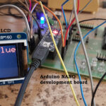
In this project the Arduino pro-mini board is used which is then programmed with the help of Arduino IDE version 1.0.3 on windows operating system. The image of the Arduino pro-mini board and the Arduino IDE is shown in the following;

Fig. 3: Typical Arduino Pro-Mini Board

Fig. 4: Arduino IDE Software Window
Another hardware which can perform the USB to TTL conversion is used to upload the program into the arduino board.

Fig. 5: External USB to TTL converter board for programming Arduino and serial communication
It is assumed that the reader has gone through the project how to get started with the arduino and done all the things discussed in it. One has to work out the character of the custom character that needs to be displayed in the LCD screen. The custom characters which are displayed in this project are shown in the following image and the section following it explains how to find out the required character pattern for each custom character.

Fig. 6: Custom Characters Created in project On LCD Using Arduino Circuit Setup On Breadboard
The LCD uses 8*8 pixel block to display each character and hence one has to assume an 8*5 array and draw the required custom character and find out the required bit pattern. One can work out with the help of the pixel array and binary array as shown in the following image.
![]()
Fig. 7: 8*5 Pixel And Binary Array For Positive Half Cycle For Custom Character
There eight rows R0 to R7 and eight columns C0 to C7. The values in all the rows and columns are now zero since all the pixels are turned off. Which all pixels need to be turned on should be given the value 1 and the rest should be kept as 0. Now read the binary pattern and write the same into the CGRAM to generate the custom character. It is advised to store the character pattern in a character array so that it would be easy to use with the C code. The pixel array and the binary array for the first custom character displayed in the project are shown in the following image;
![]()
Fig. 8: 8* 5 Pixel And Binary Array For First Custom Character
The 8 byte long character array for the above shown custom character can be defined in the code as given below;
{
0b00000,
0b00000,
0b00000,
0b00000,
0b00000,
0b00000,
0b00000,
0b11111
};
The pixel array and the binary array for the second custom character displayed in the project are shown in the following image;
![]()
Fig. 9: 8*5 Pixel and Binary Array For Second custom character using Arduino
The 8 byte long character array for the above shown custom character can be defined in the code as given below;
{
0b00000,
0b00000,
0b00000,
0b00000,
0b00000,
0b00000,
0b11111,
0b11111
};
The pixel array and the binary array for the third custom character displayed in the project are shown in the following image;
![]()
Fig. 10: Pixel and Binary Array For Third custom character using Arduino
The 8 byte long character array for the above shown custom character can be defined in the code as given below;
{
0b00000,
0b00000,
0b00000,
0b00000,
0b00000,
0b11111,
0b11111,
0b11111
};
The pixel array and the binary array for the fourth custom character displayed in the project are shown in the following image;
![]()
Fig. 11: Pixel and Binary Array For Fourth custom character
The 8 byte long character array for the above shown custom character can be defined in the code as given below;
{
0b00000,
0b00000,
0b00000,
0b00000,
0b11111,
0b11111,
0b11111,
0b11111
};
The pixel array and the binary array for the fifth custom character displayed in the project are shown in the following image;
![]()
Fig. 12: Pixel and Binary Array For Fifth custom character
The 8 byte long character array for the above shown custom character can be defined in the code as given below;
{
0b00000,
0b00000,
0b00000,
0b11111,
0b11111,
0b11111,
0b11111,
0b11111
};
The pixel array and the binary array for the sixth custom character displayed in the project are shown in the following image;
![]()
Fig. 13: Pixel and Binary Array For Sixth custom character
The 8 byte long character array for the above shown custom character can be defined in the code as given below;
{
0b00000,
0b00000,
0b11111,
0b11111,
0b11111,
0b11111,
0b11111,
0b11111
};
The pixel array and the binary array for the seventh custom character displayed in the project are shown in the following image;
![]()
Fig. 14: Pixel and Binary Array For Seventh custom character using Arduino
The 8 byte long character array for the above shown custom character can be defined in the code as given below;
{
0b00000,
0b11111,
0b11111,
0b11111,
0b11111,
0b11111,
0b11111,
0b11111
};
The pixel array and the binary array for the eigth custom character displayed in the project are shown in the following image;
![]()
Fig. 15: Pixel and Binary Array For Eighth custom character using Arduino
The 8 byte long character array for the above shown custom character can be defined in the code as given below;
{
0b11111,
0b11111,
0b11111,
0b11111,
0b11111,
0b11111,
0b11111,
0b11111
};
The Arduino IDE has a library called <LiquidCrystal.h> which provides lot of functions to access the LCD module. Few of those functions which are very useful is small applications are already discussed in the previous project on how to interface an LCD, how to display sensor value on LCD, how to connect the LCD with the PC and how to make an LCD scrolling display.
The code written for this project has a function lcd.createChar() which helps to create the custom characters in an LCD screen. The details of the lcd.createChar() function are discussed in the following section.
lcd.createChar()
The function lcd.createChar() can be used to write a custom character to the required location in the CGRAM. The function has two parameters in which the first parameter is the location in the CGRAM memory where the character array corresponding to the custom character need to be stored and the second parameter is the character array itself. For example if there is a custom character array called ‘cc’ and it need to be stored in the 5th location of CGRAM one can use the following statement;
lcd.createChar(5, cc);
The above statement writes the character array to the 5th location of the CGRAM of the LCD controller from where it can be displayed by calling the lcd.write() function discussed in the projects on how to connect the LCD with the PCand how to make an LCD scrolling display.
lcd.write(5);
You may also like:


Project Source Code
### /*================================= EG LABS ======================================= Receive a character through the serial port of the PC and display the same cahracter in a 16*2 LCD in scrolling manner along with glowing an LED each time The circuit: * LED attached from pin 5 to ground through a 1K resistor LCD: * LCD RS pin to digital pin 12 * LCD Enable pin to digital pin 11 * LCD D4 pin to digital pin 5 * LCD D5 pin to digital pin 4 * LCD D6 pin to digital pin 3 * LCD D7 pin to digital pin 2 * LCD R/W pin to ground * 10K resistor: * ends to +5V and ground * wiper to LCD pin 3 * LED anode attached to digital output 6 * LED cathode attached to ground through a 1K resistor //================================= EG LABS =======================================*/ // include the library code: #include// initialize the library with the numbers of the interface pins LiquidCrystal lcd(12, 11, 5, 4, 3, 2); //----------------- store the custom characters in arrays ---------------------// byte cc1[8] = { 0b00000, 0b00000, 0b00000, 0b00000, 0b00000, 0b00000, 0b00000, 0b11111 }; byte cc2[8] = { 0b00000, 0b00000, 0b00000, 0b00000, 0b00000, 0b00000, 0b11111, 0b11111 }; byte cc3[8] = { 0b00000, 0b00000, 0b00000, 0b00000, 0b00000, 0b11111, 0b11111, 0b11111 }; byte cc4[8] = { 0b00000, 0b00000, 0b00000, 0b00000, 0b11111, 0b11111, 0b11111, 0b11111 }; byte cc5[8] = { 0b00000, 0b00000, 0b00000, 0b11111, 0b11111, 0b11111, 0b11111, 0b11111 }; byte cc6[8] = { 0b00000, 0b00000, 0b11111, 0b11111, 0b11111, 0b11111, 0b11111, 0b11111 }; byte cc7[8] = { 0b00000, 0b11111, 0b11111, 0b11111, 0b11111, 0b11111, 0b11111, 0b11111 }; byte cc8[8] = { 0b11111, 0b11111, 0b11111, 0b11111, 0b11111, 0b11111, 0b11111, 0b11111 }; //----------------- store the custom characters in arrays ---------------------// // give the LED pin a name: int led = 6; void setup() { //---- create custom characters ----// lcd.createChar(1, cc1); lcd.createChar(2, cc2); lcd.createChar(3, cc3); lcd.createChar(4, cc4); lcd.createChar(5, cc5); lcd.createChar(6, cc6); lcd.createChar(7, cc7); lcd.createChar(8, cc8); //---- create custom characters ----// // initialize the led pin as an output. pinMode(led, OUTPUT); // set up the lcd's number of columns and rows: lcd.begin(16, 2); } void loop() { lcd.print("EG LABS "); lcd.write(1); // dispaly custom character //---- blink LED -----// digitalWrite(led, HIGH); delay(1000); digitalWrite(led, LOW); delay(1000); //---- blink LED -----// lcd.write(2); // dispaly custom character //---- blink LED -----// digitalWrite(led, HIGH); delay(1000); digitalWrite(led, LOW); delay(1000); //---- blink LED -----// lcd.write(3); // dispaly custom character //---- blink LED -----// digitalWrite(led, HIGH); delay(1000); digitalWrite(led, LOW); delay(1000); //---- blink LED -----// lcd.write(4); // dispaly custom character //---- blink LED -----// digitalWrite(led, HIGH); delay(1000); digitalWrite(led, LOW); delay(1000); //---- blink LED -----// lcd.write(5); // dispaly custom character //---- blink LED -----// digitalWrite(led, HIGH); delay(1000); digitalWrite(led, LOW); delay(1000); //---- blink LED -----// lcd.write(6); // dispaly custom character //---- blink LED -----// digitalWrite(led, HIGH); delay(1000); digitalWrite(led, LOW); delay(1000); //---- blink LED -----// lcd.write(7); //---- blink LED -----// digitalWrite(led, HIGH); delay(1000); digitalWrite(led, LOW); delay(1000); //---- blink LED -----// lcd.write(8); // dispaly custom character //---- blink LED -----// digitalWrite(led, HIGH); delay(1000); digitalWrite(led, LOW); delay(1000); //---- blink LED -----// lcd.clear(); } ###
Circuit Diagrams

Project Components
Project Video
Filed Under: Arduino., Electronic Projects
Filed Under: Arduino., Electronic Projects

Questions related to this article?
👉Ask and discuss on Electro-Tech-Online.com and EDAboard.com forums.
Tell Us What You Think!!
You must be logged in to post a comment.