In many applications, there’s a need for a constant voltage source. However, there are more constant current source applications than constant voltage sources. Most power supplies are voltage sources, including batteries and bench power.
A constant current source can be used anywhere a fixed current is required. A resistor can also be used, but the current varies based on the voltage. This would lead to variations in the output current that are noticeable.
Current sources are never truly constant as they vary with the temperature. But they can still be used as a decent constant current source.
The current source and load limit
In a constant current source, a load is connected to its output terminal and provides a constant current to the load.
But what happens to the output voltage in this situation?
The output voltage plays a critical role. If it exceeds the input limit of the current source, then the source will no longer provide a constant current. To avoid this situation, it’s necessary to choose a maximum limit of load.
There are two methods for generating a constant current source:
1. Combining transistors and operational amplifiers (op amps)
2. Using a buck regulator
Creating a constant current with LM350
In this experiment, we’ll design a constant current source using an LM350 linear buck converter. It’s a step-down converter, which reduces (or steps down) the input voltage to a desired value.
The LM350 specifications:
- Maximum output current – 3A
- Input voltage range – 1.2 to 32V.
Basic design

Block diagram of a constant current source using LM350.
Principles of operation
An adjustable linear regulator is required to design the current source.
This type of regulator consists of input, output, and a feedback pins (the adjustable pin), which feeds the output. When the input or load changes, the feedback loop regulates the output voltage.
Internally, the integrated circuit (IC) has an error amplifier (based on the op amp), a transistor, and a reference voltage source. The error amplifier monitors the output voltage, comparing it to the reference voltage of the regulator. The amplifier also tries to keep the reference voltage fixed to maintain a constant current flow through the feedback network.
So, a constant current flows through the output even at different load values.
Parts required

Circuit diagram
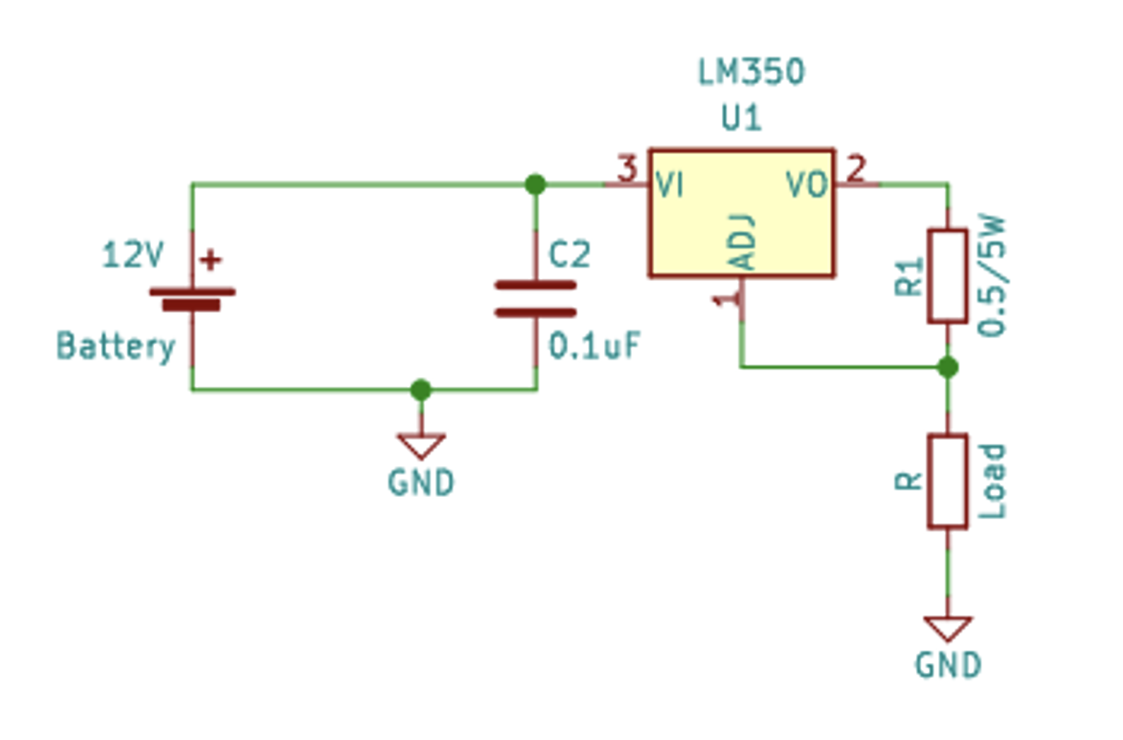
Circuit diagram of a constant current source using an LM350.
LM350 features
1. Output short circuit protection
2. Thermal overload protection
3. Safe area protection
Building the current source
Here are the steps for designing the current source.
1. Choose the output current
The LM350 provides a continuous current of 3A, so the design will have a maximum constant current source of 3A. We’ll make a 2.5A constant current source using the LM350 IC.
2. Select a feedback network
The feedback network is simply a feedback resistor network. This resistor will decide the value of the output current by maintaining a fixed voltage at the IC’s feedback pin.
Below is the equation to use for calculating the feedback resistor.
By applying the famous Ohm’s law (V = I.R), we get…

Vref = voltage reference of the regulator
LM350 regulator, Vref =1.25V
Output current , Iout = 2.5A
Feedback resistor, Rfb = Vref / Iout
Rfb = 1.25/2.5
Rfb = 0.5
1. The power rating of the feedback resistor
The high current at output causes a large amount of power dissipation through the feedback resistor. As a result, it’s necessary to calculate the exact power rating of the resistor, otherwise the resistor will start overheating and burn out.
The equation for calculating power rating of the resistor:
PR = I2*Rfb
PR = (2.5*2.5)*0.5
PR = 3.13W
2. The input capacitor
The capacitor will ensure any spike at the input will not harm the circuit. It grounds all of the ripples and spikes from the input source.
Also, to reduce the total ESR of the capacitor, we can connect a ceramic capacitor and an electrolyte.
3. Thermal management
The heat sink must be mounted with the LM350 IC because we’re using a large amount of current form it (about 2.5A). This will produce a lot of heat at the IC surface and deteriorate it. To reduce the temperature, we can use a cooling fan or a heat sink with thermal paste IC.
How the circuit works
The circuit works on the principle of a feedback loop, as already discussed. The feedback resistor continuously feeds the voltage at the output to the feedback pin, maintaining a constant voltage at the resistor.
As per Ohm’s law (V = I.R), we know that a constant current will flow by making the voltage and resistor constant. And this is exactly what the linear regulator creates here.
In our constant current source circuit, the feedback loop maintains a fixed output voltage across the feedback resistor — and the value of the feedback resistor is also constant. This allows constant current flow at the output, regardless of the load.
So, we have successfully designed a constant current source by using just one resistor and a linear regulator IC.
Connecting the load at the output
When a load is connected to its output, a constant current will flow across it, regardless of its value.
In this situation, the load “decides” the output voltage. It will take a voltage drop as per its impedance value. Therefore, before connecting any load to the output, we must consider its impedance.
Calculating the maximum load limit
The law of power conservation states that energy can neither be created nor destroyed. The linear regulators are not power converters. Rather, the input power of the linear regulator is always less than the output power. Any remaining power is dissipated in heat.
Ultimately, they provide a voltage, which is less than the input voltage.
Consider the following example to understand this concept for a linear regulator.

Vout = Vin – Vd
Vout = 12 – 2
Vout = 10V…………………………Eq.2

VR = 2.5*10
VR = 25V
However, as per the above calculation, the regulator is unable to provide 25V at the output. We must first calculate the output load limit using the following equation.

Maximum value of resistive load, RL = 4E
Thermal management
For the cooling purpose, we must connect a heat sink to the LM350 IC, which helps maintaining the IC’s temperature. Please refer to this “Power Supply Thermal Management” article to know how to select the ideal parameters of a heat sink and cooling fan.
Practical observation
- Input voltage, Vin =12V


Graph of the constant current at a load of 3 ohms.
Applications
1. Driving transistors for the amplifiers
2. Charging constant-current-based batteries
3. Lighting systems
Precautions
- Make sure the power rating of the feedback resistor is as per the stated requirement.
- Always put a load under the limits of the current source.
- A capacitor should be connected between input pin and ground to keep the DC input voltage regulated.
- The capacitor used in the circuit must be of a higher voltage rating than the input supply voltage. Otherwise, the capacitor will begin leaking the current due to the excess voltage at its plates. Eventually, it will burst.
- Make sure all the capacitor is discharged before working on a DC power supply.
- Avoid using a higher voltage at the input than its operating input voltage range.
- Do not short the output terminals — this will reverse the current flow in the IC and cause a fault.
- Do not short the input terminals — this will generate a large current in the circuit and the components will fault.
- Always connect a heat sink or a cooling fan for heat dissipation around the IC.
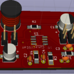
Circuit set-up
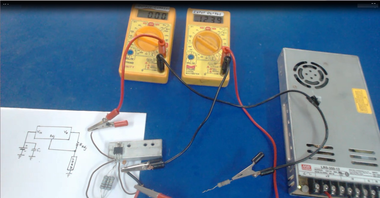
The circuit
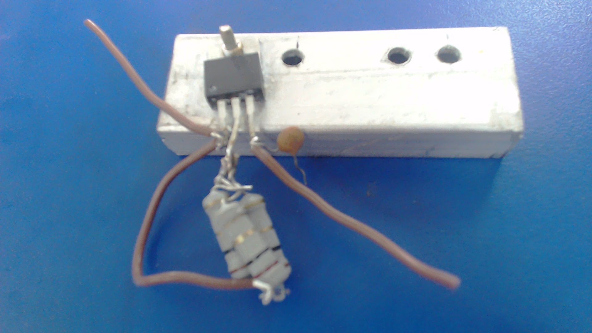
Real-time prototype image of the circuit.
You may also like:


Filed Under: Power, Tutorials

Questions related to this article?
👉Ask and discuss on Electro-Tech-Online.com and EDAboard.com forums.
Tell Us What You Think!!
You must be logged in to post a comment.