It’s been said that one of the best home security systems is owning a dog. In this do-it-yourself (DIY) circuit, we’ll design a unique system that lets you take advantage of a guard dog for security without ever needing to walk or feed it.
This DIY system “barks” like a dog whenever motion is detected near your front door, employing a radar sensor and an audio amplifier.
All that’s needed is a small gadget, which uses a special sensor to detect motion outside your door. Whenever it senses movement, it plays a loud barking sound as if there’s a dog inside. It works like a home security alarm, but requires no wires or costly, high-tech monitoring devices. Plus, this “guard dog” is easy to set up.
Let’s design the prototype.
Components
- A microcontroller (preferably Arduino UNO)
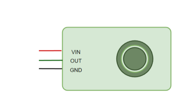
- RCWL-0516 RADAR motion sensor
- Micro SD card reader module
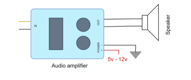
- TPA3118 PBTL Audio amplifier circuit
- A 5-10W speaker driver
- A 9v power supply/rechargeable batteries
- Male-female jumper wires
Working principle
The primary goal of this project is to create a cost-effective and easy-to-use home security system. Instead of relying solely on conventional alarms or surveillance systems, the sound of a dog barking can create a more organic deterrent against potential intruders.
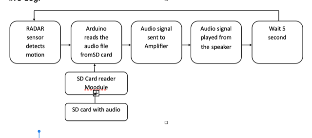
The main design components are a radar sensor and an audio amplifier. The working principle entails the following:
- Motion detection. The RADAR sensor notices motion and is extremely sensitive. When something moves in its range of five to eight meters, it sends a signal.
- Barking sound. We’ll attain the sound of a dog barking online, and save it on a memory card (Micro SD card). Whenever the RADAR senses motion, it signals Arduino, which then plays the stored barking sound from the SD card.
- Increasing the volume. Typically, Arduino’s sound is not very loud — or, at least, not loud enough to serve as a deterrent. So, we’ll need to incorporate an audio amplifier, which connects to a speaker for ample volume.
Programming Arduino
Before beginning this project, ensure you have the necessary libraries installed, including SD, SPI, and TMRpcm. The code is short and simple.
In the setup() function, we chose Pin 9 as the speaker output. Wait for the SD card to be detected with SD.begin() before setting the volume to 5 (this worked well for our audio amplifier). After a one-minute delay, the loop function begins, allowing time to get out of the sensor’s range.
In the loop() function, check if Pin 5 is receiving input (where the RADAR sensor connects). If there’s a signal, the TMRpcm library will play the audio file (bark.wav) from the SD card once. Afterward, there’s a vie-second delay to avoid continuous playback with every motion.
Preparing the audio file
Before Arduino can use the audio file, it requires processing as follows.
- Download the sound of a dog barking as an MP3.
- Used a tool to convert it to WAV.
- Make a few changes to the audio:
- Bit resolution: 8
- Audio frequency: 16000
- Audio channels: Mono
- PCM format: U8
- Save the file as ‘bark.wav.’ It’s a good idea to keep the file names short (within four characters). Some SD card readers do not work well with longer names.
Formatting the SD card
To use an SD card with the Arduino, it must be formatted to ‘FAT.’ To do so, we used the Resizer-free tool. It can be installed by running setup.exe.
Open the software, pick your drive, and click ‘format.’ Next, copy the ‘bark.wav’ audio file onto the SD card. You can use any tool to do so, but make sure to format the SD card to FAT.
Making the circuit connections
Upload the code to Arduino UNO board before connecting the circuit. The steps are the same regardless of the microcontroller.
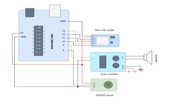
Refer to the image above for the correct Arduino GPIO pins. The circuit might appear complicated initially, but it’s easier to understand if you break it down into one part at a time.
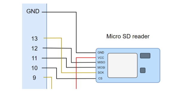
Connecting the SD card reader
Start by putting the Micro SD card into the card reader. Then, connect it to Arduino as follows:
- CS to pin 10
- SCK to pin 13
- MOSI to pin 11
- MISO to pin 12
- VCC to the 5V pin
- GND to the GND pin
This links the card reader to Arduino.
Connecting the radar sensor
- Connect VIN to Arduino’s 3.3V pin (Note: The circuit diagram might show 5V, but this is an error).
- Connect OUT to Arduino’s pin 5.
- Connect GND to Arduino’s GND pin.
This ensures the proper connections for the set-up.
Connecting the audio amplifier
- Connect the audio input pins to pin 9 and GND on Arduino.
- Power + and must be directly connected to the 9V power supply.
- The audio output pins are linked to the 6W speaker.
- These connections are standard for all audio amplifiers. If you have a stereo amplifier, you can use one channel and leave the others empty.
The power supply
For a portable, easy-to-move device, consider using rechargeable Li-ion batteries. Make sure to use a proper charging module for safe charging. Also, add a switch for turning it ON/OFF.
You’ll note for this prototype, we used a 9V power supply directly. It’s not ideal because an extra wire for the door was required, but it still worked.
The assembly
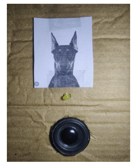
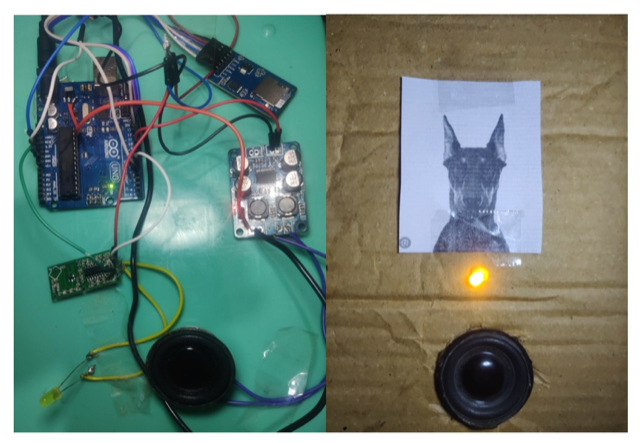
Use a cardboard box for the prototype housing, as it’s just a concept test. For the final version, you can design a 3D-printed case. We placed all the components inside except for the RADAR sensor and speaker. The RADAR sensor is attached to the back using double-sided foam tape with tiny holes for its pins. Avoid placing it inside to avoid adding thickness to the door.
Next, cut a hole in the front for the speaker, which must be secured with screws and extra layers of cardboard for strength. We added a black paper dog for fun!
The last step is attaching it to your front door using foam tape. Ensure the RADAR sensor sits flush against the door without gaps.
Final test and conclusion
This innovative project showcases how a combination of readily available components and creative thinking can enhance home security. By leveraging the power of technology — a simple RADAR sensor and an audio amplifier — it’s possible to create a convincing scenario… you own a guard dog!
An advanced project could integrate the Internet-of-things for remote control and smartphone notifications. For now, embrace the simplicity and effectiveness of a barking guardian at your doorstep.
You may also like:
Filed Under: Circuit Design, Video



Questions related to this article?
👉Ask and discuss on Electro-Tech-Online.com and EDAboard.com forums.
Tell Us What You Think!!
You must be logged in to post a comment.