Engineers Garage

  • Projects and Tutorials
    • Electronic Projects
      • 8051
      • Arduino
      • ARM
      • AVR
      • PIC
      • Raspberry pi
      • STM32
    • Tutorials
    • Circuit Design
    • Project Videos
    • Components
  • Articles
    • Tech Articles
    • Insight
    • Invention Stories
    • How to
    • What Is
  • News
    • Electronic Products News
    • DIY Reviews
    • Guest Post
  • Forums
    • EDABoard.com
    • Electro-Tech-Online
    • EG Forum Archive
  • Digi-Key Store
    • Cables, Wires
    • Connectors, Interconnect
    • Discrete
    • Electromechanical
    • Embedded Computers
    • Enclosures, Hardware, Office
    • Integrated Circuits (ICs)
    • Isolators
    • LED/Optoelectronics
    • Passive
    • Power, Circuit Protection
    • Programmers
    • RF, Wireless
    • Semiconductors
    • Sensors, Transducers
    • Test Products
    • Tools
  • EE Resources
    • DesignFast
    • LEAP Awards
    • Oscilloscope Product Finder
    • White Papers
    • Webinars
  • EE Learning Center
    • Design Guides
      • WiFi & the IOT Design Guide
      • Microcontrollers Design Guide
      • State of the Art Inductors Design Guide
  • Women in Engineering

How To Interrupt The Arduino Board Periodically- (Part 26/49)

By Ajish Alfred

The interrupt is a method by which a microcontroller is made to divert from current path of code execution to do some other important things that needs immediate processing. The code which is written to process whenever an interrupt occurs is called an Interrupt Service Routine (ISR). Once an interrupt occurs the controller stops its current processing and start executing the ISR and returns back to the previous task once it finish the ISR. This particular project explains how to make a variable frequency generator with the help of Arduino.The Arduino is referred to as an easy prototyping platform which has been popular among both hobbyist and experts and widely used in industries as well. Any AVR microcontroller based board which follows the standard Arduino schematic and is flashed with the Arduino bootloader can be called an Arduino board.

The Arduino board can be programmed for generating digital output, PWM output and square waves of different frequencies. This particular project demonstrates how to generate the square wave using Arduino board which can be used for periodically interrupting the same Arduino board itself. The periodical interrupts are very important and are used to perform certain tasks which need to be performed continuously at fixed interval of time like sampling of a wave form as an example.


The working of this project is explained based on the Arduino pro-mini board and the IDE version 1.0.3 for windows. The advantage of this board is that it comes in very small in size; any kind of connectors can be soldered on its periphery according to our requirements. It is very breadboard friendly and occupies very less space of a typical breadboard.

The image of the arduino pro-mini board and the arduino IDE are shown below;

 Typical Arduino Pro-Mini Board

Fig. 2: Typical Arduino Pro-Mini Board


 Arduino IDE Software Window

Fig. 3: Arduino IDE Software Window

Since the arduino pro-mini board has no circuitary for interfacing it with the serial port or the USB port of the PC, an external USB to TTL converter board is required to connect it with the PC. This hardware helps in programming the arduino board and also helps in the serial communication with the USB port of the PC.

External USB To TTL Converter Board For Programming Arduino And Serial Communication

Fig. 4: External USB to TTL converter board for programming Arduino and serial communication

It is assumed that the reader has gone through the project how to get started with the arduino and tried out all the things discussed there.The Arduino IDE provides some functions to make use of the interrupt features of the Arduino board. The code written for this project make use of functions attachInterrupt() and detachInterrupt() which can be used to enable an interrupt on either of the two external interrupt pins or disable an already enabled interrupt respectively. The details of the functions are discussed in the following section;

attachInterrupt()

The function attachInterrupt() is used to enable an interrupt on either of the two external interrupt pins along with configuring the type of triggering and also assigning an ISR to be executed whenever an interrupt occurs. The function has three variables, the first one is the pin number at which the interrupt signals expected to appear and the second one is the function which can act as the ISR. The third parameter defines the method of triggering.

The prototype of the function is given as the following;

void attachInterrupt ( interrupt_pin, isr_function, trigger_method );

The return type of the function is declared as void and hence the function returns nothing. The first parameter is the interrupt pin which determines at which pin the interrupt should be enabled as mentioned below;

{C}–          interrupt_pin

0 for enabling the interrupt on pin2

1 for enabling the interrupt on pin3

The second parameter points to the function which should be made as the ISR. The parameter should be provided with the name of the function which is required to act as an ISR.

The third parameter defines the kind of triggering that should be enabled on the interrupt pin mentioned by the first parameter. The four different values and their details that can be applied to the third parameter are given below;

{C}–         trigger_method

LOW to trigger the interrupt whenever the pin is low,

CHANGE to trigger the interrupt whenever the pin changes value

RISING to trigger when the pin goes from low to high,

FALLING for when the pin goes from high to low.

The functions that help in interrupt programming and the method of generating interrupts are already discussed in previous project on how to use interrupt with the Arduino board.

The Arduino IDE also provides two functions namely tone() and noTone() for start generating a square wave at a particular frequency and to stop the square wave respectively. The details of the functions are already discussed previous projects on how to generate square wave with Arduino board  and how to make a simple variable frequency generator with the Arduino board.

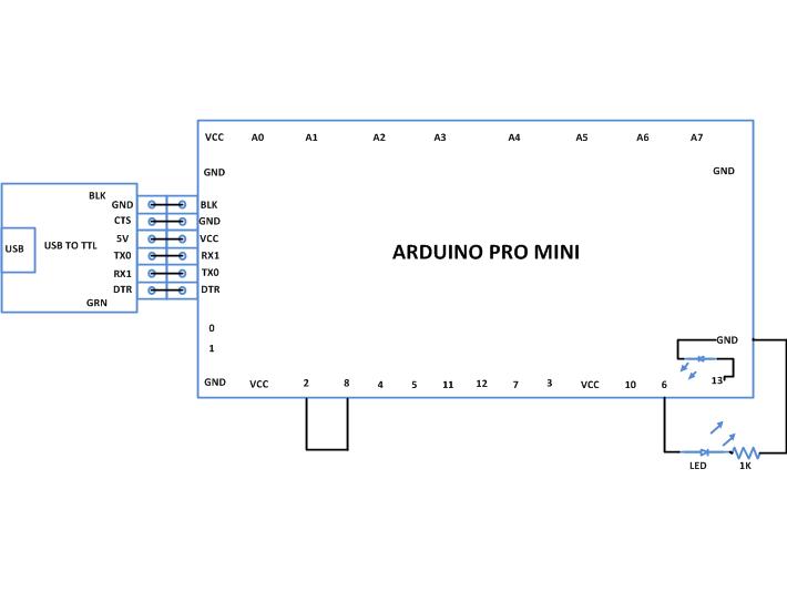
The code generates a square wave of frequency 0.1 Hz on the pin number 8 of the Arduino board. The pin number 8 is then shorted with the 0th external interrupt pin which has been configured to trigger an input on the rising edge of a clock. The ISR has a code which inverses the state of an LED using the functions digitalWrite() which has been discussed in the previous projects on how to get started with the Arduino and how to use the digital input and output of an Arduino. 

When the coding is finished one can verify and upload the code to the Arduino board as explained in the project how to get started with the Arduino. The waveform can generated at the pin number 8 can be observed using a CRO which is connected to the pin number 8. It can also be observed that the LED is continuously blinking at a particular low frequency.

Project Source Code

###


/*================================= EG LABS =======================================

The demonstration on how to interrupt the Arduino board periodically


 * Short the pin number 8 and pin number 2 

 * LED attached from pin 6 to ground through a 1K resistor

================================== EG LABS =======================================*/


int led = 6;                                         // variable indicating the pin number where the LED is connected

int led_state = 0;                                   // variable indicating the state of the LED              


void setup()

{             

  pinMode(led, OUTPUT);                              // initialize the digital pin as an output.


  attachInterrupt(0, glow, RISING);                 // enable the external interrupt 0, with function 'glow' as ISR and interrupt occurs on rising edge


  tone(8, 0.1);

}


void loop()

{

  digitalWrite(led, led_state);                      // turn the LED on or off depending on the value of the 'led_state'

}


//========== ISR ============//

void glow()

{

  led_state = !led_state;                             // invert the value of the led_state

}

//========== ISR ============//

###


Circuit Diagrams

Circuit-Diagram-Interrupting-The-Arduino-Board-Periodically

Project Components

  • Arduino Pro Mini
  • LED
  • Resistor

Project Video


Filed Under: Arduino
Tagged With: Arduino, interrupt
 

Questions related to this article?
👉Ask and discuss on EDAboard.com and Electro-Tech-Online.com forums.


Tell Us What You Think!! Cancel reply

You must be logged in to post a comment.

HAVE A QUESTION?

Have a technical question about an article or other engineering questions? Check out our engineering forums EDABoard.com and Electro-Tech-Online.com where you can get those questions asked and answered by your peers!


Featured Tutorials

  • PS2 Keyboard To Store Text In SD Card Using Arduino Circuit Setup On Breadboard
    How To Use PS2 Keyboard To Store Text In SD Card Using Arduino- (Part 42/49)
  • Wireless Path Tracking System Using Mouse, XBee And Arduino Circuit Setup On Breadboard
    How To Make A Wireless Path Tracking System Using Mouse, XBee And Arduino- (Part 43/49)
  • How to Make a Wireless Keyboard Using Xbee with Arduino- (Part 44/49)
  • Making Phone Call From GSM Module Using Arduino Circuit Setup On Breadboard
    How to Make Phonecall From GSM Module Using Arduino- (Part 45/49)
  • How to Make a Call using Keyboard, GSM Module and Arduino
    How To Make A Call Using Keyboard, GSM Module And Arduino- (Part 46/49)
  • Receiving SMS Using GSM Module With Arduino Prototype
    How to Receive SMS Using GSM Module with Arduino- (Part 47/49)

Stay Up To Date

Newsletter Signup

Sign up and receive our weekly newsletter for latest Tech articles, Electronics Projects, Tutorial series and other insightful tech content.

EE Training Center Classrooms

EE Classrooms

Recent Articles

  • Renesas delivers intelligent sensor solutions for IoT applications
  • Microchip Technology releases AVR-IoT Cellular Mini Development Board
  • Qualcomm acquires Cellwize to accelerate 5G adoption and spur infrastructure innovation
  • MediaTek’s chipset offers high-performance option for 5G smartphones
  • Nexperia’s new level translators support legacy and future mobile SIM cards

Most Popular

5G 555 timer circuit 8051 ai Arduino atmega16 automotive avr bluetooth dc motor display Electronic Part Electronic Parts Fujitsu ic infineontechnologies integratedcircuit Intel IoT ir lcd led maximintegratedproducts microchip microchiptechnology Microchip Technology microcontroller microcontrollers mosfet motor powermanagement Raspberry Pi remote renesaselectronics renesaselectronicscorporation Research samsung semiconductor sensor software STMicroelectronics switch Technology vishayintertechnology wireless

RSS EDABOARD.com Discussions

  • about ATmega328 ADC pins
  • Tuning the antenna to be conjugately matched to input impedance of the die
  • Netlist physical name update
  • nt1065_USB3 gnss receiver
  • LLC HB with synchronous rectifiers can be very dodgy?

RSS Electro-Tech-Online.com Discussions

  • undefined reference header file in proteus
  • Capacitor to eliminate speaker hum
  • Decapped Chip On Board
  • Sony KV-A2913E (chassis AE1C) auto shuts off after one minute
  • CRT TV repair
Engineers Garage
  • Analog IC TIps
  • Connector Tips
  • DesignFast
  • EDABoard Forums
  • EE World Online
  • Electro-Tech-Online Forums
  • Microcontroller Tips
  • Power Electronic Tips
  • Sensor Tips
  • Test and Measurement Tips
  • 5G Technology World
  • About Us
  • Contact Us
  • Advertise

Copyright © 2022 WTWH Media LLC. All Rights Reserved. The material on this site may not be reproduced, distributed, transmitted, cached or otherwise used, except with the prior written permission of WTWH Media
Privacy Policy | Advertising | About Us

Search Engineers Garage

  • Projects and Tutorials
    • Electronic Projects
      • 8051
      • Arduino
      • ARM
      • AVR
      • PIC
      • Raspberry pi
      • STM32
    • Tutorials
    • Circuit Design
    • Project Videos
    • Components
  • Articles
    • Tech Articles
    • Insight
    • Invention Stories
    • How to
    • What Is
  • News
    • Electronic Products News
    • DIY Reviews
    • Guest Post
  • Forums
    • EDABoard.com
    • Electro-Tech-Online
    • EG Forum Archive
  • Digi-Key Store
    • Cables, Wires
    • Connectors, Interconnect
    • Discrete
    • Electromechanical
    • Embedded Computers
    • Enclosures, Hardware, Office
    • Integrated Circuits (ICs)
    • Isolators
    • LED/Optoelectronics
    • Passive
    • Power, Circuit Protection
    • Programmers
    • RF, Wireless
    • Semiconductors
    • Sensors, Transducers
    • Test Products
    • Tools
  • EE Resources
    • DesignFast
    • LEAP Awards
    • Oscilloscope Product Finder
    • White Papers
    • Webinars
  • EE Learning Center
    • Design Guides
      • WiFi & the IOT Design Guide
      • Microcontrollers Design Guide
      • State of the Art Inductors Design Guide
  • Women in Engineering