The scrolling display boards are the most attractive among all kind of display boards. They are widely used in advertisements, used in public transport vehicles, used as information boards in railway station, airport etc. They are commonly made of LEDs or LCD screen and are usually connected to a computer or a simple microcontroller which can send the data to the screen.
A normal LCD module found in the embedded system devices can be made as a scrolling display. It can respond to built-in scrolling commands which make the LCD scrolling possible. It is possible to connect the serial port of the PC with the LCD module through the Arduino board. In such a system the user can send the data from the PC to the Arduino’s serial port using software running in the PC, and can view the same data in the LCD module connected to the Arduino board and that in a scrolling manner if the necessary statements are written in the code.
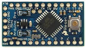
The AVR microcontroller boards which are provided with all the basic circuitry for the operation of the microcontroller which has been flashed with the Arduino boot-loader are called Arduino boards. The Arduino can communicate with the other devices using its digital I/O, serial port, I2C port, SPI port etc.

Fig. 2: Typical Arduino Pro-Mini Board

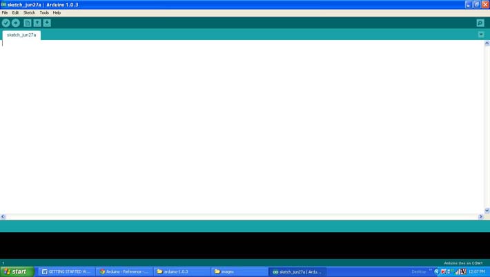
Fig. 3: Arduino IDE Software Window
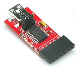
Since the Arduino pro-mini board has no circuitary for interfacing it with the serial port or the USB port of the PC, an external USB to TTL converter board is required to connect it with the PC. This hardware helps in programming the Arduino board and also helps in the serial communication with the USB port of the PC.

Fig. 4: External USB to TTL converter board for programming Arduino and serial communication
It is assumed that the reader has gone through the project how to get started with the Arduino and tried out all the things discussed there.
This project uses function for accessing LCD module available from the library <LiquidCrystal.h> as explained in the previous project on how to interface the 4 bit LCD with Arduino board. The serial communication functions are also used in this project which is already discussed in a previous project on how to receive and send serial data using Arduino.
Apart from those functions this project make use of two more functions for the LCD namely lcd.write() and lcd.autoscroll() the details of them are discussed in the following section.
lcd.write()
Thelcd.write() also a function which is used to print the data to the LCD screen like the lcd.print() function does. Unlike the lcd.print() function the lcd.write() function directly write the value to the LCD screen without formatting it as ASCII. This function is analogues to the Serial.write() function discussed in the project how to receive and send serial data using Arduino.
lcd.autoscroll()
This function is called after initializing the LCD module using the lcd.begin() function and after setting the cursor position using the lcd.setCursor() function. This function make the scrolling possible by shifting the current displayed data to either side of the LCD as each characters are written into the LCD screen.
THE CODE
The code initializes the LCD library as per the connection of the LCD with the Arduino board using the function LiquidCrystallcd(). The function lcd.begin() is used to initialize the LCD module in four bit mode with two line display. The lcd.setCursor() function is used to set the cursor at the 16th position of the second line of the 16*2 LCD from where the scrolling is supposed to start.
The serial port is initialized with 9600 baud rate using the function Serial.begin(). The function Serial.available() is used in the code to check whether a serial data is available to read or not.
The Serial.read() function is used to read the serial data coming from the PC which is then stored to a variable and is displayed on the LCD using the function lcd.write().
// include the library code:
#include <LiquidCrystal.h>
// initialize the library with the numbers of the interface pins
LiquidCrystallcd(12, 11, 5, 4, 3, 2);
// give the pin a name:
int led = 6;
// incoming byte
charinByte;
void setup()
{
// initialize the led pin as an output.
pinMode(led, OUTPUT);
// set up the LCD’s number of columns and rows:
lcd.begin(16, 2);
// initialize the serial communications:
Serial.begin(9600);
// set the cursor to (16,1):
lcd.setCursor(16,1);
// set the display to automatically scroll:
lcd.autoscroll();
}
void loop()
{
// if we get a valid byte, read analog ins:
if(Serial.available())
{
// get incoming byte:
inByte = Serial.read();
// send the same character to the LCD
lcd.write(inByte);
// glow the LED
digitalWrite(led, HIGH);
delay(200);
}
else
digitalWrite(led, LOW);
}
Whenever a key is pressed in the keyboard the code receives the data byte and sends the same byte to display it in the LCD screen after shifting the current display to one side. The code also blinks an LED each time it transmits a data to the serial port using the functions pinMode (), digitalWrite () and delay (). The details of those functions are already discussed in the previous project on How to use digital input and digital output of the Arduino board.
Project Source Code
###


/*================================= EG LABS =======================================

 Receive a character through the serial port of the PC and display the same cahracter

 in a 16*2 LCD in scrolling manner along with glowing an LED each time

 The circuit:

 * LED attached from pin 5 to ground through a 1K resistor

 LCD:

 * LCD RS pin to digital pin 12

 * LCD Enable pin to digital pin 11

 * LCD D4 pin to digital pin 5

 * LCD D5 pin to digital pin 4

 * LCD D6 pin to digital pin 3

 * LCD D7 pin to digital pin 2

 * LCD R/W pin to ground

 * 10K resistor:

 * ends to +5V and ground

 * wiper to LCD pin 3

 * LED anode attached to digital output 6

 * LED cathode attached to ground through a 1K resistor

//================================= EG LABS =======================================*/

// include the library code:

#include <LiquidCrystal.h>

// initialize the library with the numbers of the interface pins

LiquidCrystal lcd(12, 11, 5, 4, 3, 2);

// give the pin a name:

int led = 6;

// incoming byte

char inByte;

void setup()

{

  // initialize the led pin as an output.

  pinMode(led, OUTPUT);

  // set up the LCD's number of columns and rows:

  lcd.begin(16, 2);

  // initialize the serial communications:

  Serial.begin(9600);

  // set the cursor to (16,1):

  lcd.setCursor(16,1);

  // set the display to automatically scroll:

  lcd.autoscroll();

}

void loop()

{

  // if we get a valid byte, read analog ins:

  if(Serial.available())

  {

    // get incoming byte:

    inByte = Serial.read();

    // send the same character to the LCD

    lcd.write(inByte);

    // glow the LED

    digitalWrite(led, HIGH);

    delay(200);

  }

  else

    digitalWrite(led, LOW);

}

###
Circuit Diagrams
Project Components
Project Video
Filed Under: Arduino
Filed Under: Arduino


Questions related to this article?
👉Ask and discuss on EDAboard.com and Electro-Tech-Online.com forums.
Tell Us What You Think!!
You must be logged in to post a comment.