Sensors are used to convert a physical quantity, such as light intensity or temperature, into an electrical one. There are several types of sensors that can easily be used with an Arduino board, which is an advantage.
For example, any analog or digital sensor easily interfaces with Arduino as the board offers both analog and digital inputs. Analog sensors collect readings over a range of values and digital sensors read if a signal is active (high or low).
Potentiometer, joystick, and temperature sensors are examples of analog sensors. IR proximity, vibration, and flame or smoke sensors are digital ones. All of these sensors can directly connect with Arduino, displaying their values on a serial monitor. Displays, such as LCD or 7-segment LED, can be used to present a sensor’s value.
The OLED — or organic light-emitting diode — is another display option and serves as an alternative to the LCD. Where an LCD is passive, the OLED is active (meaning it contains amplifiers). It’s also small, bright, and extremely lightweight, which is why it’s commonly used in hand-held or pocket-sized portable gadgets.
The OLED allows for plenty of display options, including text, digits, shapes, and images. Here we’ll learn how to display a sensor value, starting with the display basics and how to interface OLED with an Arduino board.

The OLED display used in this project is approximately 1 x 1” in dimension (typically referred to as the 1-inch display). It has a built-in display controller, the SSD1306.
Features include:
1. 128×64 pixels
2. High contras
3. I2C communication protocol
4. Dual color (blue and yellow)
5. No backlight required
6. Active type display
One of the advantages of this type of display is that its pixels only consume energy when they are on. This means the OLED consumes less power compared to most other displays.
As shown in the above diagram, the display has four pins. Only two — the SDA and SCL pins — are required for interfacing. For this project, the VCC pin is given 5 Volts of power supply.
The display works on the I2C communication protocol, a single-ended, serial communication bus, which uses only two pins here: the SDA and SCL. (This is why it’s known as TWI or the two-wire interface).
The host microcontroller must use the I2C protocol to display the value, whether as a text message, digits, a shape (such as a circle or square), an image. It can even display basic animations. To do so with Arduino, you’ll need to use the Adafruit library.
Simply install these two libraries from Adafruit:
- Adafruit_ssd1306.h
- Adafruit_GFX.h
These two libraries provide full control of the OLED sensor display. Let’s review the circuit diagram next.
Circuit

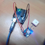
Circuit connections
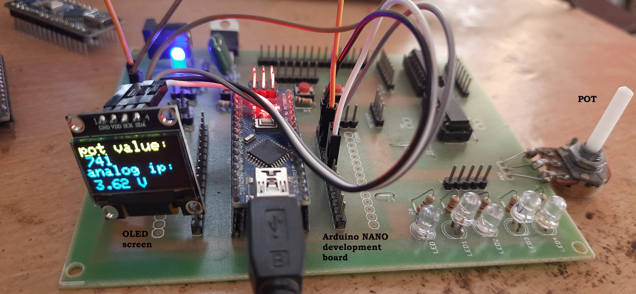
As shown in the above diagram, the circuit is built using three components:
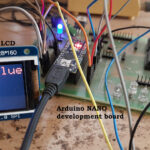
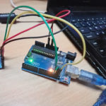
1. The Arduino NANO board
2. An OLED display
3. A potentiometer (POT)
- The PT has three terminals. Connect the two end-terminals with Arduino’s +5V and GND pins. The middle pin is a slider, which connects to Arduino’s analog input pin A0.
- The OLED has four interfacing pins: the VCC, GND, SDA, and SCL. Connect the VCC and GND pins with Arduino’s +5 V and GND pins. This provides power to the display. Next, connect the SDA and SCL pins with Arduino’s A4 (SDA) and A5 (SCL) pins for data communication.
- The Arduino board requires a USB power supply (from a computer). The onboard, voltage-regulator chip provides a 5-V supply to the POT and OLED display.
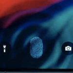
Circuit operation
- The POT is given a power supply of +5 V. Depending on how far its knob is rotated, it provides 0 to 5 V analog output voltage via the center slider terminal.
- This analog voltage output is, then, fed to Arduino’s analog input pin A0. Arduino reads the input and provides a corresponding digital output number between 0 and 1023. The digital output is showcased on the OLED display as “POT Value.”
- Next, Arduino once again converts the digital value (of between 0 and 1023) into an analog voltage between 0 to 5 V as follows:
Digital value | Analog voltage
1023 5 V
X X × (5 / 1023)
- Arduino presents the analog voltage on the display as “voltage ip.”
- Ultimately, the analog and digital values are displayed on the OLED.
Software
The Arduino board (ATMega328) performs the following tasks, given the below software program:
1. Reads the POT’s analog voltage input and converts it into a digital value
2. Converts the digital value into an analog voltage
3. Showcases the analog and digital values on the OLED display
This program is written in C/C++ language using the Arduino IDE software. It’s compiled and uploaded using the same software.
Code
The YouTube video link for this project:
You may also like:

Filed Under: Electronic Projects, Sensors
