The name itself suggests that the project is on industrial automation and the application is developed to control any industrial DC motor. Lets first check the specifications
Motor type: – DC series motor
Maximum Rated Voltage:- 100 VDC
Maximum rated current: – 4 Amp
Power ratings: – 2 HP
Maximum RPM: – 3000
Torque: – 5 to 10 Kg/cm2
This is completely different project than other ones. It’s an industrial application and is specifically designed for industries like textile, plastic, chemical etc.
The program controls the motion of motor by two modes (1) continuous mode (2) see-saw mode
In continuous mode one can change the speed and direction of motor. The motor starts with minimum speed in selected direction and gradually reaches to maximum speed. Desired rise time (the time given to motor to reach maximum speed) and fall time (time given to motor gradually decrease the speed and then stop) can be chosen for the motor.
In between the operation one can increase / decrease RPM in four steps. Also the direction can be immediately changed on a single click.
See-saw mode is specially designed for some applications like weaving bobbin, cutting with hacksaw-blade mixing colors or other chemicals etc. In this mode the motor first rotates clockwise for some time (entered by user) and then automatically changes the direction to anticlockwise. Again after same time has passed, motor will change direction. So this CW-CCW rotation continuous till motor is stopped.
Complete project is divided in two sections
(1) Hardware Part :- it includes PWM generator, amplifier and H-Bridge driver
(2) Software part: – program written in VC++ generates all switching signals like changing speed, and direction etc.
First let’s starts with hardware part
Hardware Part:-
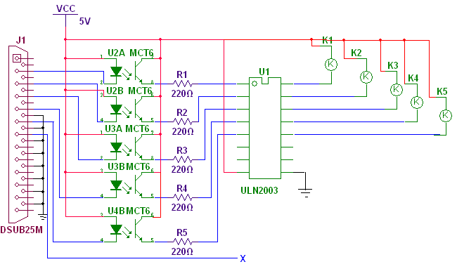
The complete circuit is too big so i have divided it in two parts. One part contains opto couplers, ULN chip and relays. Second part contains PWM generator and H-bridge driver circuit. The figure given below is first part of circuit.
Connections: – As shown in figure five opto-couplers are used to drive relays through ULN chip using LPT port of PC. The anodes and collectors of every opto-couplers are tied with Vcc. The cathode of each opto-coupler is connected with data pins D0(2) – D4(6). Emitters of each opto-coupler are connected to inputs of ULN chip through current limiting resistors. Outputs of ULN drive relay coils.
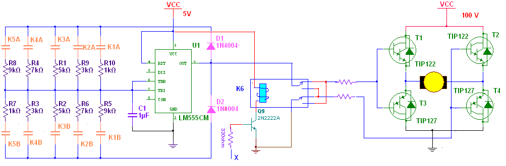
The figure in Circuit Diagram tab2 shows rest of the part of circuit. IC555 is configured in astable mode to generate rectangular wave output. Width of o/p pulse changes depending upon the relay is energized because relay will change the combination of resistors. To make a h-bridge circuit 4 Darlington pairs are used. Relay K6 is used to change direction of motor. The connections of Nc/No pins are made such a way that when one side of h-bridge receives PWM other is connected to ground.
Operation: –
- When anyone sends low logic on data pins of LPT that makes opto-coupler turn on.
- So it will send high output to input of ULN
- That will energize particular relay and pair of resistors are connected with iC555
- So it will start generating WPM that is given to h-bridge circuit
- This will start rotating motor in one direction with some set speed.
- Now as any one switch ON/OFF different relays the width of o/p pulse will change due to different pair of resistors. So the speed of motor will change.
- To change direction of motor one has to switch on relay K6.
Software
Software Section:-
Below is the screen shot for computerize industrial control panel for DC motor.

Let’s first see the entire object IDs and its properties.
There are total 8 buttons, 5 static texts, 2 Edit boxes and 2 group boxes in whole application
|
Sr. No. |
Object |
Property |
Setting |
|
1 |
button |
ID Caption |
IDC_FWD Start Forward |
|
2 |
button |
ID Caption |
IDC_REV Start Reverse |
|
3 |
button |
ID Caption |
IDC_STP Stop Motor |
|
4 |
button |
ID Caption |
IDC_INC Increase |
|
5 |
button |
ID Caption |
IDC_DEC Dencrease |
|
6 |
button |
ID Caption |
IDC_STRT Start |
|
7 |
button |
ID Caption |
IDC_STOP Stop |
|
8 |
button |
ID Caption |
IDC_XIT Exit the Program |
|
9 |
Static text |
ID Caption |
IDC_STATIC -: controlling panel for industrial DC motor:- |
|
10 |
Static text |
ID Caption |
IDC_STATIC Enter rise time and fall time in sec :- |
|
11 |
Static text |
ID Caption |
IDC_STATIC Enter time interval in sec:- |
|
12 |
Static text |
ID Caption |
IDC_STATIC Count:- |
|
13 |
Static text |
ID Caption |
IDC_CNT 0 |
|
14 |
Edit box |
ID |
IDC_TIME |
|
15 |
Edit box |
ID |
IDC_INTV |
|
16 |
Group box |
ID Caption |
IDC_STATIC Speed |
|
17 |
Group box |
ID Caption |
IDC_STATIC See-Saw effect |
After completing the designing of application one has to start coding. Before that he has to attach three variables to IDC_CNT, IDC_TIME and IDC_INTV. Attach a variable named m_intv of integer type with IDC_INTV and m_itime of same type with IDC_TIME. Attach m_scnt of string type with IDC_CNT.
Now add two variables to Dialog class of integer type named m_c and m_t. Then attach function with each button and after that start coding. Please refer the table given below for the function of each button.
|
Sr. No |
Button |
Function |
|
1 |
Start Forward |
Gradually starts the motor in one direction from minimum speed to maximum speed in four steps in selected rise time. |
|
2 |
Start Reverse |
Gradually starts the motor in other direction from minimum speed to maximum speed in four steps in selected rise time. |
|
3 |
Stop motor |
Gradually decrease the speed of motor in two steps in selected fall time |
|
4 |
Increase |
Increase the speed of motor by one step |
|
5 |
Decrease |
Decrease the speed of motor by one step |
|
6 |
Start |
Start the see-saw effect and automatically reverse the motor after entered time |
|
7 |
Stop |
Stop the see-saw effect |
|
8 |
Exit the program |
Exit the program |
One more thing that remains is adding timer / counter into the application. Because this is the first application where timer is used follow the step by step procedure
- Open classwizard from view menu and choose resource symbols from menu
- You will see that all the above IDs that you have created are in the list. You have to add one more ID to handle timer event.
- So now click new button. Give name ID_CNT_TMR and set value 1.
- At last you have one new ID created to handle timer event
- Some functions related to timer are SetTimer, KillTimer and OnTimer that are used in coding.
Project Source Code
Project Source Code
###
void CAutotimerDlg::OnStrt()
{
// TODO: Add your control notification handler code here
SetTimer(ID_CNT_TMR,1000,NULL); // start timer when start button
m_ic = 0; // is pressed with 1 sec delay
m_scnt.Format("%d",m_ic);
}
void CAutotimerDlg::OnTimer(UINT nIDEvent)
{
// TODO: Add your message handler code here and/or call default
UpdateData(TRUE);
if(m_ic != m_intv)
{
m_ic++; // update the count after every sec
m_scnt.Format("%d",m_ic); // and display it
if((c%2)==0) // change the direction after entered
{
_outp(0x0378,0x12); // time interval
//MessageBox("Motor is running reverse");
}
else
{
_outp(0x0378,0x32);
//MessageBox("Motor is running forward");
}
}
else if(m_ic = m_intv)
{
c++;
m_ic = 0;
m_scnt.Format("%d",m_ic);
}
UpdateData(FALSE);
CDialog::OnTimer(nIDEvent);
}
void CAutotimerDlg::OnStop()
{
// TODO: Add your control notification handler code here
KillTimer(ID_CNT_TMR); // stop see-saw effect
_outp(0x0378,0x00);
}
void CAutotimerDlg::OnFwd()
{
// TODO: Add your control notification handler code here
f=0;
UpdateData(TRUE);
m_t = m_itime*250;
MessageBox("motor has started in forward direction");
_outp(0x0378,0x11); // increase the speed gradually to maximum
Sleep(m_t); // with entered rise time
_outp(0x0378,0x12);
Sleep(m_t);
_outp(0x0378,0x14);
Sleep(m_t);
_outp(0x0378,0x18);
c1 =4;
MessageBox("motor has attained full speed");
UpdateData(FALSE);
}
void CAutotimerDlg::OnRev()
{
// TODO: Add your control notification handler code here
f=1;
UpdateData(TRUE);
m_t = m_itime*250;
MessageBox("motor has started in reverse direction");
_outp(0x0378,0x31); // increase the speed gradually to maximum
Sleep(m_t); // with entered rise time
_outp(0x0378,0x32);
Sleep(m_t);
_outp(0x0378,0x34);
Sleep(m_t);
_outp(0x0378,0x38);
c1 =4;
MessageBox("motor has attained full speed");
UpdateData(FALSE);
}
void CAutotimerDlg::OnStp()
{
// TODO: Add your control notification handler code here
UpdateData(TRUE);
m_t = m_itime*500;
if(f == 0)
{
MessageBox("motor was running in forward direction");
_outp(0x0378,0x12); // gradually stops the motor
Sleep(m_t); // in two steps with entered
_outp(0x0378,0x11); // delay
Sleep(m_t);
_outp(0x0378,0x00);
MessageBox("Motor is stopped");
}
else
{
MessageBox("motor was running in reverse direction");
_outp(0x0378,0x32);
Sleep(m_t);
_outp(0x0378,0x31);
Sleep(m_t);
_outp(0x0378,0x00);
MessageBox("Motor is stopped");
}
}
void CAutotimerDlg::OnInc()
{
// TODO: Add your control notification handler code here
if(c1 != 4) c1++;
else if (c1 = 4)
{
c1=1;
MessageBox("Maximum speed");
}
if(f == 0)
{
switch(c1)
{
case 1:
_outp(0x0378,0x11);
MessageBox("Speed is 1");
break;
case 2:
_outp(0x0378,0x12);
MessageBox("Speed is 2");
break;
case 3:
_outp(0x0378,0x14);
MessageBox("Speed is 3");
break;
case 4:
_outp(0x0378,0x18);
MessageBox("Speed is 4");
break;
}
}
else
{
switch(c1)
{
case 1:
_outp(0x0378,0x31);
break;
case 2:
_outp(0x0378,0x32);
break;
case 3:
_outp(0x0378,0x34);
break;
case 4:
_outp(0x0378,0x38);
break;
}
}
}
void CAutotimerDlg::OnDec()
{
// TODO: Add your control notification handler code here
if(c1 != 1) c1--;
if(f == 0)
{
switch(c1)
{
case 1:
_outp(0x0378,0x11);
MessageBox("Speed is 1");
break;
case 2:
_outp(0x0378,0x12);
MessageBox("Speed is 2");
break;
case 3:
_outp(0x0378,0x14);
MessageBox("Speed is 3");
break;
case 4:
_outp(0x0378,0x18);
MessageBox("Speed is 4");
break;
}
}
else
{
switch(c1)
{
case 1:
_outp(0x0378,0x31);
break;
case 2:
_outp(0x0378,0x32);
break;
case 3:
_outp(0x0378,0x34);
break;
case 4:
_outp(0x0378,0x38);
break;
}
}
}
void CAutotimerDlg::OnXit()
{
// TODO: Add your control notification handler code here
OnOK();
_outp(0x0378,0x00);
}
###
Circuit Diagrams
Filed Under: Electronic Projects

Questions related to this article?
👉Ask and discuss on Electro-Tech-Online.com and EDAboard.com forums.
Tell Us What You Think!!
You must be logged in to post a comment.