AC Drive is widely used and probably a vital controlling device in the field of industrial automation. Most of manufacturing industries, continuous production units, chemical industries, textiles miles, pharmaceutical industries are now equipped with most advance industrial automation and to control various AC motors the ultimate solution is AC Drive.
What’s an AC Drive?
AC Drive is actually a kind of inverter, but the main difference is it gives variable frequency variable voltage (vfvv or it may be vvvf or V3F) output. Basic building block of any AC drive is converter, filter, inverter and switching control circuit. The switching control circuit is the heart of drive and it controls the output of inverter to produce vfvv.
Now a days AC Drives are available with enhance features like display unit (7 segment or LCD), user interface (keypad), programmability, different operating modes, etc. more advance AC drives can be configured in master-slave configuration many of them have serial interface to directly communicate with PC through hyper terminal.
Here I have experimented with one of very popular AC Drive which is used to control 3 HP, 3 Ø AC Motor. The drive is fully programmable. Its programming instructions are given in user manual. We have to program the drive for remote operation. The appropriate terminals are provided on drive Terminal Extension Board (TEB) through which we can take out connections to operate drive from a remote place.
General description: –
The normal controlling operation that can be perfor med on AC drives are start, stop, reset, and increase / decrease motor speed. In increasing or decreasing motor speed there are two modes. One is auto and other is manual. In manual mode either we can vary the speed by varying potentiometer or through push buttons. In auto mode the speed changes according to industrial standard 0-10 VDCsupply or 4-20 mA current from any type of transducer.
Here I am explaining two cases, one with combine (auto & manual) mode and second with only manual mode. Given figure shows the arrangement for both cases and also shows common relay driving circuit using chip ULN2003A. Let’s see each case.
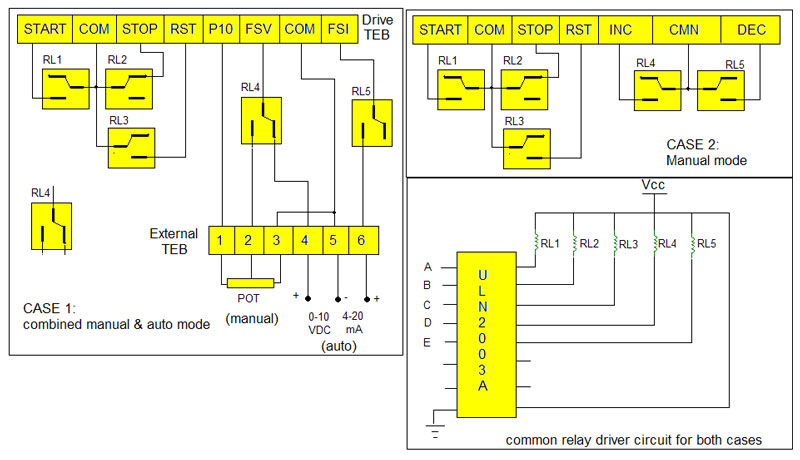
Case 1 (combine mode):- as I said there is TEB provided on drive it self through which we can take out the connection for remote operation. As one can see 8 terminals of Drive TEB are used and they are start, stop, reset, P10, FSV, FSI, Inc, Dec and com. Let’s understand what’s the use of each terminal.
Start: – a momentary or constant contact on this terminal will start the drive
Stop: – a momentary disconnection will stop the drive
Reset: – a momentary contact will reset the operation of drive
P10: – this provides +Ve voltage to potentiometer
FSV: – variable voltage from 0-10 VDC is applied here to change drive speed
FSI: – variable current of 4-20 mA is applied here to change drive speed
Inc: – a momentary contact will increase the speed by some amount
Dec: – a momentary contact will decrease the speed by some amount
Com: – this is ground of drive
As shown in figure 5 relays are used for different functions. All the relays are change over type and they are connected as shown. The external TEB is given on front panel of drive where client can connect their sources. Functions of relays are described in given table
|
RELAY |
Function |
|
RL1 |
To start the drive |
|
RL2 |
To stop the drive |
|
RL3 |
To reset the drive |
|
RL4 |
To change drive speed either by pot. (manual)or by 0-10 V supply (auto) |
|
RL5 |
To change drive speed by 4-20 mA current |
Note: – RL4 and RL5 are switched in such manner that in auto mode drive speed changes either by voltage or current. Simultaneously both voltage and current should not change speed of drive.
Case 2 (manual mode): – in this case again 5 relays are used. First 3 relays have same function but last two relays are used to vary the speed of drive manually. When RL4 and RL5 are switched momentary the drive speed will increase or decrease. So here the drive speed changes manually only.
Relay driver circuit
Relay driver circuit: –for both the cases same type of circuit can be used. The current driver chip ULN2003A is used to provide sufficient current to relay coils. Also free wheeling diode is given inbuilt in this chip. For more details see datasheet of ULN2003A.
The inputs to this chip A to E are connected with outputs of remote control receiver that we shall discuss later.
Now let’s see how these relays are switched through remote control. There are two parts remote control and its receiver unit. Both are micro-controller base. The remote control transmits a different code for each key press through IR transmitter. Receiving unit receives this code and switches on or off particular relay.
Remote control: –
Figure in Circuit Diagram1 tab shows schematic diagram for remote control. Main components are 89C51, IC555 and nand gate IC 74LS00. The heart of system is 89C51. 5 switches are connected to port P1 to perform different functions.
|
Switch |
Function |
|
S1 |
Press this key to start drive |
|
S2 |
Press this key to stop drive |
|
S3 |
Press this key to reset the drive |
|
S4 |
For case 1: press this key to change the mode from auto to manual For case 2: press this key to increase drive speed |
|
S5 |
For case 1: no use For case 2: press this key to decrease drive speed |
Operation: –When any key is pressed controller will transmit a particular code through its Tx pin (P3.1).This code is given to IC555 through nand gate. It will work as modulator. IC555 will modulate the code with carrier frequency of 38 KHz and transmit it on IR channel.
Here is the snap of transmitter unit.

Receiving unit
Receiving unit: –
The schematic diagram of receiving unit is as shown in Circuit Diagram 2 tab. There is only one main component and its 89C51.
Operation: –the IR sensor TSOP will receive 38KHz IR signal and after demodulating it gives it to 89C51. After receiving the code 89C51 will switch the particular relay through o/p port P2 and gives indication on LEDs connected to port P0. Please refer the table.
|
LED |
Color |
Indication |
|
LED1 |
Green |
Stays ON to indicate drive is running |
|
LED2 |
Red |
Stays ON to indicate drive is stop |
|
LED3 |
Yellow |
Blinks when reset pulse is applied to drive |
|
LED4 |
Blue |
For case 1: no use For case 2: blinks when drive speed is increased |
|
LED5 |
Blue |
For case 1: no use For case 2: blinks when drive speed is decreased |
|
LED6 |
Red |
For case 1: stays on when drive is in manual & FSI mode For case 2: no use |
|
LED7 |
Green |
For case 1: stays on when drive is in auto (FSV) mode For case 2: no use |

Programs for both micro-controllers are written in C language with help of micro vision keil cross compiler.
Project Source Code
Project Source Code
###
// Code for Transmitter: #include<reg51.h> void send(void); //function to transmit byte serially void main() { TMOD=0x20; // set timer 1 in mode 2 SCON=0x40; // set mode 1 for serial comu TH1=0xF3; // set baud rate as 9600 bps TL1=0xF3; TR1=1; // start timer 1 loop:P1=0xFF; // P1 as input port while(P1==0xFF); // wait until any key press switch(P1) // check which key is pressed { case 0xFE: // for first key ACC='a'; // send code 'a' send(); break; case 0xFD: // for second key ACC='b'; // send code 'b' send(); break; case 0xFB: // same as above ACC='c'; send(); break; case 0xF7: ACC='d'; send(); break; case 0xEF: ACC='e'; send(); break; } goto loop; // jump to continu loop } void send(void) { SBUF=ACC; // move byte to sbuf SFR while(TI==0); // wait until transmission completes TI=0; } Code for Receiver (Case 2): #include<reg51.h> unsigned char c; sbit rst = P0^2; // reset indicator sbit inc = P0^3; // speed increase indicator sbit dec = P0^4; // speed decrease indicatorvoid delay (void) // 1 ms delay
{
int x;
for(x=0;x<1000;x++);
}
void recv(void) interrupt 4 // interrupt subroutine to receive byte
{
RI=0;
c=SBUF; // get received byte
delay();
}
void main()
{
TMOD=0x20; // set timer 1
SCON=0x40; // initialize serial commu.
TH1=0xF3; // set baud rate
TL1=0xF3;
P0=0xFF;
P2=0x00;
TR1=1; // start timer
IE=0x90; // enable serial interrupt
REN=1; // enable reception
loop:c=0x00;
while(c==0x00); // loop until nothing is received
switch(c) //
{
case 'a':
P2=0x01; // give pulse on P2.0 to start drive
P0=0xFE; // give indication
delay();
P2=0x00;
break;
case 'b':
P2=0x02; // give pulse on P2.1 to stop drive
P0=0xFD; // give indication
delay();
P2=0x00;
break;
case 'c':
P2=0x04; // give pulse on P2.2 to reset drive
rst=0; // blink reset led
delay();
rst=1;
P2=0x00;
break;
case 'd':
P2=0x08; // give pulse on P2.3 to increase speed
inc=0; // blink increase speed led
delay();
inc=1;
P2=0x00;
break;
case 'e':
P2=0x10; // give pulse on P2.4 to decrease speed
dec=0; // blink decrease speed led
delay();
dec=1;
P2=0x00;
break;
}
goto loop; // jump to continuous loop
}
// Code for Receiver (Case 1):
#include<reg51.h>
unsigned char c;
sbit rst = P0^2; // reset indication
sbit aut = P0^5; // auto mode indication
sbit man = P0^6; // manual mode indication
void delay (void) // 1 ms delay
{
int x;
for(x=0;x<1000;x++);
}
void recv(void) interrupt 4 // interrupt based data reception
{
RI=0;
c=SBUF;
delay();
}
void main()
{
TMOD=0x20; // set timer 1
SCON=0x40; // initialize serial commu.
TH1=0xF3; // set baud rate
TL1=0xF3;
P0=0xFF;
P2=0x00;
TR1=1; // start timer 1
IE=0x90; // enable serial interrupt
REN=1; // enable reception
loop:c=0x00;
while(c==0x00); // loop until nothing is received
switch(c)
{
case 'a':
P2=0x01; // same as case 2
P0=0xFE;
delay();
P2=0x00;
break;
case 'b':
P2=0x02;
P0=0xFD;
delay();
P2=0x00;
break;
case 'c':
P2=0x04;
rst=0;
delay();
rst=1;
P2=0x00;
break;
case 'd':
P2=0x18; // select auto mode
aut=0; // give indication
man=1;
break;
case 'e':
P2=0x00; // select manual mode
aut=1;
man=0;
break;
}
goto loop; // jump to continuous loop
}
###
Circuit Diagrams


Filed Under: Electronic Projects

Questions related to this article?
👉Ask and discuss on EDAboard.com and Electro-Tech-Online.com forums.
Tell Us What You Think!!
You must be logged in to post a comment.