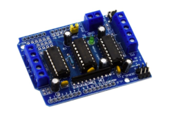
The Arduino L293D motor driver shield guide is a robobtics project that involves driving various types of motors. The most common types used for robotic applications include DC, servo, and stepper motors. However, these motors typically cannot be driven directly by Arduino or another microcontroller. This is because of their higher current and power ratings,…
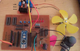
How to control DC motor speed & direction using a joystick and Arduino
Much like the name suggests, DC motor controllers control the speed and direction of a DC motor. To change the direction of the motor, however, the supply it receives must be reversed. And, to vary the DC motor speed, a pulse-width modulation (PWM) signal or wave must be applied to it. As the pulse width…
Simple DC Motor Controller using 555 Timer IC
Controller is actually a combination of two circuits – driver circuit and Switching circuit. Driver is the actual circuit that drives DC motor and switching circuit decides how DC motor should be driven. So actually, switching circuit is the main circuit that controls the motor. Now there are two parameters of DC motor that can be controlled Speed and Direction.Changing the direction of DC motor is very simple just reverse the supply given to DC motor. For varying speed of motor you have to vary the applied DC voltage. One well known method widely used in industries is Pulse Width Modulated (PWM) speed control of DC motor also known as chopper control.
Microcontroller Based Sequential Timer for DC Motor Control
In most of the manufacturing industries, it is required to rotate DC/AC motor forward and reverse alternatively for desired time. First motor rotates forward (clockwise) for some time (say few minutes or even seconds). Then it stops for some time. Again it rotates reverse (anticlockwise) for some time and stops. This process continues. For example, in automated bottle filling plant, the bottles are moving on conveyor belt. When it comes under filler, the filler comes down (that means motor attached with mechanism rotates forward) then it fills the bottle (that means motor stops) again it goes up (motor rotates reverse) and stops until next bottle arrives. For moving filler up and down the time of rotating motor forward and reverse is calibrated and fixed. Also the motor stop time is calibrated based on time required to fill the bottle and the next bottle arrives.
DIY- Emergency Phone Charger using a DC Motor
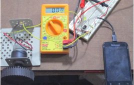
During power outages, and all the batteries around your home drain away, the only option left for you would be this. This tutorial shows you how to charge a phone using a 12V DC motor and a couple of other parts.A DC motor can also work as a DC generator and vice-versa since their construction and operating principle are similar. So I would be using a 12V DC geared motor as a generator since we need a power source to charge our device.
DC Motor Speed Control by Cell Phone
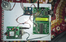
We can control the speed of the single phase DC Motor with ease by using microcontroller and proper driving mechanism.In industries mostly coil based analog variable frequency drive is used. Because of this type of variable frequency drive there are problem rising like over current, short circuit, over voltage, under voltage, under frequency which results in unwanted tripping of the devices.We can replace this coil based analog variable frequency type with microcontroller based speed controlling mechanism. Because of this type of speed controlling, we can accurately control the speed of DC motor in operation. In addition to this, this type of controlling comparatively cheaper, reliable and accurate .It requires less maintenance and it is more convenient in use.Aim of this project is to control speed of dc motor using commands sent from mobile phone. As speed of dc motor is dependent on duration of input voltage, by changing the duration we can control the speedof the single phase dcmotor.
DC Motor Control with Joystick & AVR Microcontroller
In many of the applications it is required to alter the direction of DC motor instantly. Like in washing machine, mixer, drilling machine winding – rewinding machine etc. Changing the direction of DC motor using joystick is most suitable and handy method.In industries the joystick control is most preferable way to control machinery that is operated with DC motor. The best example is 3 axis or 2 axis DC motor operated crane. In this, 3 (or 2) DC motors moves crane up or down, rotate it left or right using 3 (or 2) joysticks
Speed and Direction Control of DC Motor using AVR Microcontroller – (Part 20/46)
we can count number of such applications where there is a need to change direction and/or speed of DC motor. The direction of DC motor can be controlled by just reversing the polarity of given supply. And for varying speed, there are various ways to vary speed of DC motor but the best amongst them is PWM – pulse width modulation technique. In this technique we shall vary the width of applied pulse that will vary average voltage applied to motor and its speed will change.
Speed Control Using PWM
Today’s industries are increasingly demanding process automation in all sectors. Automation results into better quality, increased production an reduced costs. The variable speed drives, which can control the speed of A.C/D.C motors, are indispensable controlling elements in automation systems. Depending on the applications, some of them are fixed speed and some of the variable speed drives. The variable speed drives, till a couple of decades back, had various limitations, such as poor efficiencies, larger space, lower speeds, etc., However, the advent power electronic devices such as power MOSFETs, IGBTs etc., and also with the introduction of micro -controllers with many features on the same silicon wafer, transformed the scene completely and today we have variable speed drive systems which are not only in the smaller in size but also very efficient, highly reliable and meeting all the stringent demands of various industries of modern era.
Speed Control of DC Motor Using PID Method
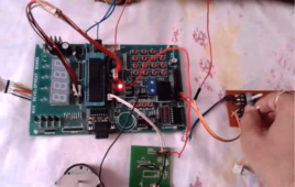
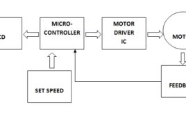
The development of high performance motor drives is very important in industrial as well as other purpose applications. Generally, a high performance motor drive system must have good dynamic speed command tracking and load regulating response. The dc motors are used in various applications such as defense, industries, Robotics etc. DC drives, because of their simplicity, ease of application, reliability and favorable cost have long been a backbone of industrial applications. The project provides the efficient and simple method for control speed of DC motor using ATMEGA16 microcontroller and L298N motor driver IC.With the use of ATMEGA16 and l298N we can drive the dc motor at desired speed having a feedback loop and in this project we have used proportional integral and derivative method in which errors are not only solved but also taken to its minimal value with very low amount of error oscillations.
DC Gear motor rotation control
Here is very useful application that controls the number of rotation of 12 V DC gear motor with very low RPM (1,2,3,5 or 10 etc).You may find lots of [[wysiwyg_imageupload::]]applications of this project in robotics, CNC machines, manufacturing industries etc. Here are some of the examples In any PCB cutting or PVC pipe cutting CNC machine (or any other automatic cutting machine) first the linear dimensions are calibrated in terms of number of rotations (e.g. 5 rotations = 1 CM), then by adjusting the number of rotations as per required dimension one can easily move the cutting tool to that distance (e.g. for 1 meter 500 rotations). In robotic arm application, if the arm has to move to a specific position then first its movement can be calibrated in terms of number of rotations of motor. Afterwards once we program and set the number of rotations for a button, the arm will always move to that position when that button is pressed.
DC Motor Control with VC++
This project is Microsoft Windows based program written in Visual C++ to control DC motor. Visual C++ is one of the very efficient, effective more user [[wysiwyg_imageupload::]]friendly software. Let us see the main function as well as the additional features of this application. Mouse as well as keyboard interface provided. All the controlling actions at your fingertips Four degree of motion control is achieved for single motor. (1) Motor rotates continuously at constant speed (2) pulse wise rotation means motor rotates for less than one revolution (3) motor rotates with desired speed for fix duration of time (4) motor rotates till mouse button is pressed and moved. One can vary both the parameters of motor speed and direction. DC motor will rotate like stepper motor in pulse wise rotation mode. Keep on reading to find out how simple controls over DC motor can be managed using Visual C++.
How to use a PMDC Motor in Electronic Circuits
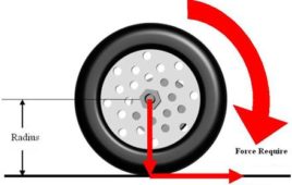
Electric motors are the most convenient devices in use which can convert the electrical energy into mechanical energy. Electrical motors converts the electrical [[wysiwyg_imageupload::]]energy to rotational motion which can then be easily converted to any kind of mechanical motion like moving a robotic arm, moving a needle in a sewing machine etc. The Permanent Magnet Direct Current (PMDC) motors are especially useful since they are very easy to control, produce a lot of power and come in various sizes, shapes and voltage ratings. When used with electrical or electronic circuits one must be careful about certain things like the current consuming, torque, RPM etc. This article mainly discusses those things and also the details of circuits which can be used to drive the PMDC motors. Continue reading to find out how PMDC motor can be easily used in electronic circuits.
Cell phone operated Robotic Arm
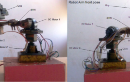
This is also picked and place type robotic application. But this has a unique feature that it is controlled from cell phone. It’s all the movements are controlled from any cell phone. That means you can control this robot from anywhere in the world where GSM / CDMA network service is available. Isn’t it very interesting??!!!!????…..The robot has built in GSM / CDMA cell phone that receives signals from other cell phone. One has to call the number of the cell phone (that is inside robot) from his cell phone to activate it. Then by pressing different keys from 0 – 9 form the phone he can control the movements of the robot. It is 4-axis robotic arm. It’s all four motions are controlled by 2 DC gear motors and 2 servo motors.Let us start with mechanical structure of robot.
Remote controlled DC Drive
In most of the industries for motion control AC motor or DC motor are used. To control the motion there is a need of either AC drive or DC drive. The basic functions of this drive are to give smooth start to motor change the direction, change the speed etc. Here I am demonstrating one such…
Industrial control panel for DC Motor
The name itself suggests that the project is on industrial automation and the application is developed to control any industrial DC motor. Lets first check the specifications Motor type: – DC series motor Maximum Rated Voltage:- 100 VDC Maximum rated current: – 4 Amp Power ratings: – 2 HP Maximum RPM: – 3000 Torque: – 5 to…
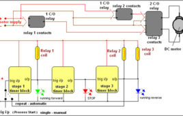
Three Stage Sequential Timer for DC motor control
In most of the industrial processes it is required to rotate DC (or AC) motor forward and reverse for desired time. First motor rotates forward (clockwise) for some time (say 2 – 3 min) then it stops for some time. Again it rotates reverse (anticlockwise) for some time and rests. This process repeats every time when gets triggeredSequential timer is widely used circuit in industries because in most of the industries all the processes are of chain reaction type. That means one process ends and it triggers next. The last process triggers first process when it ends. And thus the cycle continues. These sequence timers are micro controller based multi-functional and programmable.But here we have a sequential timer using simple IC555. So let us see how it is done
Wireless DC Motor Speed Control using IR and IC555
This is a very interesting application. We shall vary the speed of DC motor from a remote place without any wire connection. I am using PWM (pulse width modulation) method to very the speed of DC Motor. To make it wireless I am using IR transmitter and IR sensor. There are two sections in the circuit 1) PWM generator with IR modulator and 2) IR receiver and motor driver. Transmitter generates PWM wave of 50 Hz (20 ms) and modulates it over 38 KHz frequency. The IR sensor on receiver side will demodulate the PWM wave and drives the DC motor.
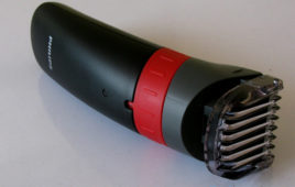
Insight – How Electric Beard Trimmer Works
We currently live in the era of speed and sophistication. Everything that man once developed and found to be too time consuming and cumbersome has been modified, altered and compacted to make its use more simple. To cope up with this speed, every routine work has been automated. This pursuit of professional excellence has forced people to spend less time on themselves. For example, shaving is almost a daily chore for men to ensure personal hygene and needs to be done fast. But doing so with manual razors is a time consuming job and if done to hastily, can lead to cuts and burns.But thankfully, the technology of this age offers replacement to old age instruments like manual razors and frequent visits to a barber shop by time effective handheld devices like hair clippers and beard trimmers. Unlike manual razors and scissors, trimmers are devices that cut, but don’t bite and that too in very less time.
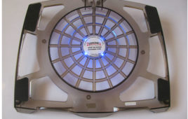
Insight – How Laptop Cooling Pad works
With time and usage, many laptops face a common problem of overheating. It not only reduces efficiency of the laptop but can also cause damage to laptop peripherals such as hard disks or microprocessor. In order to assist laptop cooling fans, USB powered cooling pads have caught the fancy of computer enthusiasts and are widely in demand all over. Light weighted and economic, cooling pads boast of keeping the laptops temperatures within tolerable limits even during prolonged spells of extensive usage. Let’s have a look at a typical laptop cooling pad. The laptops are placed with the tilted side facing the user so that they can have easy access to keyboard. The laptop is held on the tilt structure through the rubber sponge pads that are placed at the edges of the cooling pad.Cooling pads are generally made of light weight plastic or aluminum mesh or a combination of both.

