Temperature controllers are used in most of the manufacturing industries. The industries like textile mill, pharmaceutical industry, oil refinery etc. all requires temperature controller. The temperature controllers are used to maintain constant temperature of process or plant or any material. In such temperature controller system there is one reference temperature called set point or set temperature that is the desired temperature that must be maintained. This reference temperature is set by external means. Also it can be always adjustable according to requirements. Once this temperature is set the system tries to maintain it by sensing the current temperature and controlling it using heater, cooler or compressor etc.
It senses current temperature, compares it with reference temperature and generates error signal. Then based on this error signal it controls heating element (or cooling element). If set temperature is more then error signal is negative and vice versa.
So here I have given one such temperature control system that senses current temperature using temperature sensor. It compares it with the set temperature that is set by external reference. And it gives indication of error signal as positive or negative.
· If error is positive that means current temperature is more than set temperature that has to be reduced
· If error is negative that means current temperature is less than set temperature and it is required to increase it
System Block Diagram:

Fig. 1: Overview of Industrial Temperature Control System
As shown in above figure, major building blocks of system are temperature sensor, Analog to Digital Converter (ADC), micro-controller, LCD, clock generator and LED indicators.
Temperature sensor: It’s a transducer. It gives corresponding voltage (or current) output as change in temperature. It can be calibrated to degree Celsius. Otherwise it has to be calibrated first.
Reference potentiometer: It sets reference temperature between min to max value. The system operation depends upon this set temperature value.
ADC: Its analog to digital converter with built in multiplexer. It takes two analog inputs one from temperature sensor and another from reference potentiometer. It gives 8-bit digital output corresponding selected analog input. To get the digital output of any one channel, micro controller will select the required channel and takes digital output.
Clock generator: ADC requires clock signal for its operation. This clock signal is generated by IC555 based clock generator.
Micro controller: it controls operation of ADC and LCD. It takes digital output of both channels and displays them on LCD. It takes suitable decision by comparing two temperatures. Also it gives different indications on LEDs
LED indicators: shows different indications like

Fig. 2: Table listing LED Indicators in Industrial Temperature Control System
Connections
Connections: –
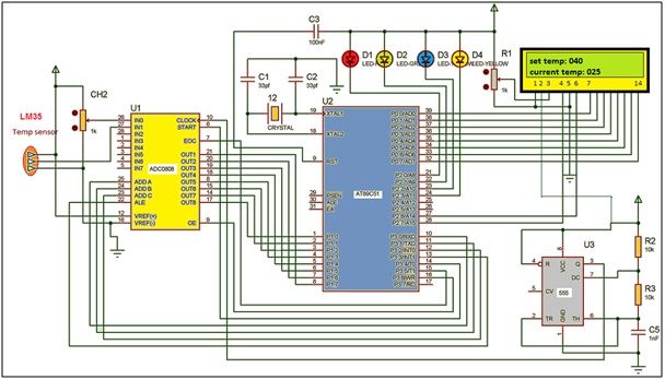
· LM35 temperature sensor is connected to channel 2 (IN1) of ADC0808. It will sense the current temperature and gives analog voltage output as 10 mV / oC
· A 1K pot is connected to channel 1 (IN0) of ADC0808. It will set the reference temperature between 0 to 255
· The data signals (OUT1 – OUT8) are connected to port P1 of microcontroller 89C51. So micro controller gets digital value of current/set temperature on port P1.
· The control signals START, EOC and OE of ADC0808 are connected to port P3 pins P3.4, P3.5 and P3.6 respectively. These pins are used to control ADC operation like start conversion, enable output, check end of conversion etc.
· The channel select pins ADD A, ADD B, ADD C and ALE pin are also connected to port P3 pins P3.0 to P3.4. these pins selects one of the 8 input channel for conversion
· IC555 is connected in astable mode. Its output frequency is approx 50 KHz. Its output is given to clock input of ADC. IC555 generates required clock signal for ADC0808
· Port P0 is connected to data pins (D0 – D7) of LCD. So data to be displayed on LCD or commands are given to LCD from P0. Two control pins RS and E of LCD are connected to P2.7 and P2.7 respectively. RW pin is grounded.
· A 1K pot is connected with LCD as shown. It varies the brightness.
· Port P2 pins P2.0 to P2.3 drives four different colour LEDs as shown. So these pins gives various indications through LEDs
· A 12 MHz crystal along with two 33 pf capacitors is connected to crystal input pins XTAL1 and XTAL2. This gives basic clock of 12 MHz to micro controller.
Working & Operations
Working and operation:
· Microcontroller first latches address of channel 1 in to ADC. Then it asserts start signal to start conversion. It waits for end of conversion (EOC) signal from ADC. When it gets it, it takes digital input from P1 and after processing it displays it on LCD as set temperature
· Next microcontroller latches address of channel 2. Again it asserts start signal and waits for EOC. When it gets EOC, takes digital input – process it – displays it on LCD as current temperature
· Then microcontroller take difference of these two temperature values that is the error. If error is positive then it indicates this on BLUE LED. If error is negative then it gives indication on YELLOW LED
· This process is continuously repeated after every two second
Further extension
The project can be further extended. The error signal output can be used to control any heating or cooling element that will change the temperature. The change in temperature is continuously monitored using temperature sensor. So this becomes complete close loop control system. The system will try to automatically maintain the set temperature value by getting feedback and generating +Ve or –Ve error signal.
Project Source Code
###

// This program is written in C language. It is compiled, simulated and debugged using KEIL IDE. Here is the program
#include<reg51.h >
#include<string.h>
sbit ale=P3^3;
sbit oe=P3^6;
sbit sc=P3^4;
sbit eoc=P3^5;
sbit a=P3^0;
sbit b=P3^1;
sbit c=P3^2;
sbit rs=P2^7;
sbit en=P2^6;
sbit led1=P2^0;
sbit led2=P2^1;
sbit led3=P2^2;
sbit led4=P2^3;

void delay()                                         // 2 sec delay
  {
            int x,y;
            for(x=0;x<40;x++)
              for(y=0;y<10000;y++);
  }

void busy()                                          // lcd busy function
{
            int x;
            for(x=0;x<1500;x++);
}

void writecmd(unsigned char a)           // send command byte to LCD
{
            busy();
            rs = 0;
            P0 = a;
            en = 1;
            en = 0;
}

void writedata(unsigned char b)           // send data byte to LCD
{
            busy();
            rs = 1;
            P0 = b;
            en = 1;
            en = 0;
}

void writestr(unsigned char *s)            // write string / message to LCD
{
            unsigned char l,i;
            l = strlen(s);
            for(i=0;i<l;i++)
            {
                        writedata(*s);
                        s++;
            }
}

void display(unsigned char z)              // convert HEX to decimal and
  {                                        //decimal to ASCII for display
            unsigned int tmp1,tmp2,t,t1,a;
            unsigned char asci[3];
            tmp1 = (z & 0x0F);
            tmp2 = z >> 4;
            tmp2 = tmp2*16;
            t = tmp1+tmp2;
            if(t>=100)
              {
                        a=2;
                        while(t>=10)
                        {
                                    t1=t%10;
                                    asci[a]=t1+0x30;
                                    t=t/10;
                                    a--;
                          }
                        asci[0]=t+0x30;
              }
            else
              {
                        t1=t%10;
                        asci[2]=t1+0x30;
                        t=t/10;
                        asci[1]=t+0x30;
                        asci[0]=0x30;
              }
            writedata(asci[0]);
            writedata(asci[1]);
            writedata(asci[2]);
  }

void main()
  {
            unsigned char data byt1,byt2;
            unsigned int c1=0;
            P0=0x00;
            P1=0xFF;
            P2=0x00;
            P2=0x0F;
            P3=0x20;
            writecmd(0x3C);
            writecmd(0x0E);
            writecmd(0x01);
            writestr("  Temperature");
            writecmd(0xC3);
            writestr("controller");
            delay();
            writecmd(0x01);
            while(1)
              {
                        c1++;
                        if(c1==1) {a=0;b=0;c=0;led1=0;led2=1;} // select ADC
                        else {a=1;b=0;c=0;led1=1;led2=0;} // channels alternatively
                        ale=1;
                        sc=1;                                        // start conversion
                        ale=0;
                        sc=0;
                        while(eoc==1);             // wait for end of conversion
                        while(eoc==0);
                        oe=1;                                       // enable output
                        if(c1==1) byt1=P1 ;     // get digital value
                        else byt2=P1;
                        oe=0;
                        if(c1==1)
                        {
                                    writecmd(0x80);
                                    writestr("set temp:");    // display set
                                    display(byt1);                          // temperature
                        }
                        else
                          {
                                    writecmd(0xC0);                         // display current
                                    writestr("current temp:");         // temperature
                                    display(byt2);
                                    if(byt2<=byt1) {led3=0;led4=1;} // indicate error
                                    else {led3=1;led4=0;}                         // on LEDs
                                    c1=0;
                          }
                        delay();                                         // delay for 2 second
              }
            }
 ###
Circuit Diagrams
Project Video
Filed Under: Electronic Projects
Filed Under: Electronic Projects

Questions related to this article?
👉Ask and discuss on EDAboard.com and Electro-Tech-Online.com forums.
Tell Us What You Think!!
You must be logged in to post a comment.