The first ever mouse was made by Douglas Engelbart of Stanford Research Center in 1963. It was one of the major inventions in computing world which supported keyboard to a large extent, making the experience of working on computer easier and faster. Since its invention different technologies have been developed to improve the efficiency of a mouse. A ball mouse is a type of electro mechanical device which uses a small ball as the key component to determine its movements and speed.
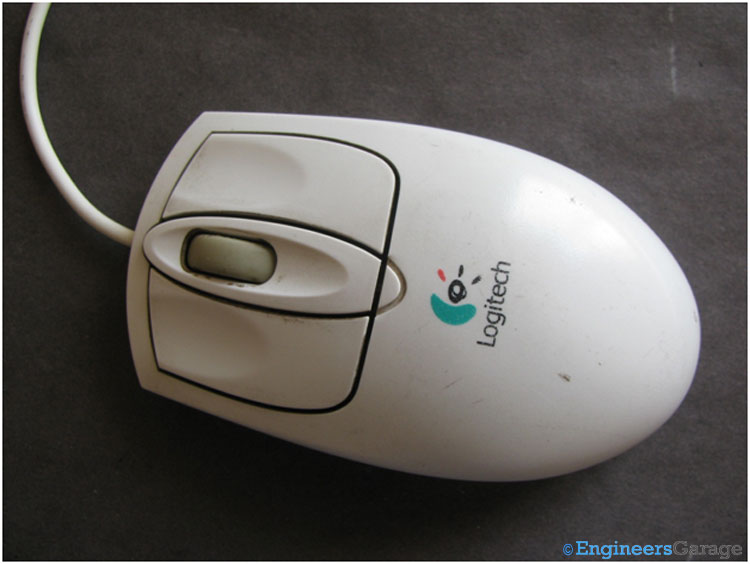
Fig. 1: Image of 4-Input Ball Mouse of Computer
A ball mouse is shown in the image. It has four inputs– left click, center click, right click and a scrolling wheel.
Bottom View
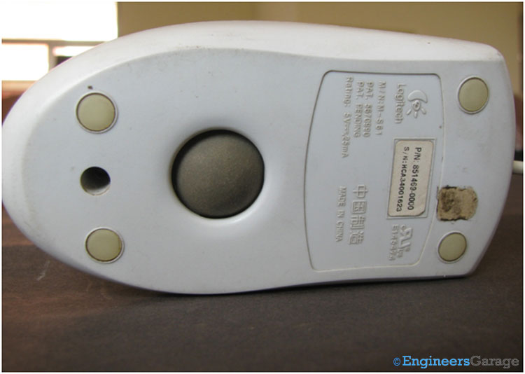
Fig. 2: Image Showing Ball at Backside of Computer Mouse
The backside portion of the mouse shows the ball which is the heart of the ball mouse. When placed over a surface it rotates with the movement of the mouse. The ball mouse needs a flat surface with enough friction for smooth rotation of the ball and hence is generally accompanied with a mouse pad.
Internal Structure
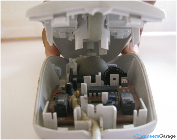
Fig. 3: Internal Structure and Mechanism of Mouse
The above image shows a glimpse of the internal structure of the mouse.
Top & Bottom Assembly
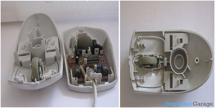
Fig. 4: (a) Top and Bottom Parts of Mouse. (b) Internal Layout of Top of Mouse
The above image shows the top and bottom parts of the mouse. This top half is connected to the bottom half through mechanical hooks and screws. The various parts of the top half segment are shown in the right side image . The mechanical structure plays an important role. It holds the scrolling wheel, supports the ball and provides mechanical motion to different parts for left, right and center click.
Rollers
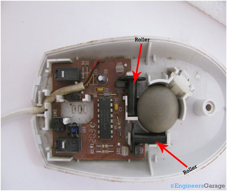
Fig. 5: A Close View of Internal Mechanism of Lower Part of Mouse
When the hand moves the mouse, the ball starts rotating accordingly. The ball is in mechanical contact with two rollers, which in turn rotates with the motion of the ball. Each roller is made up of a cylindrical shaft with a special disk attached at one end of the shaft. The two rollers are placed perpendicular to each other to detect the motion in the X and Y direction.
Sensor Mechanism
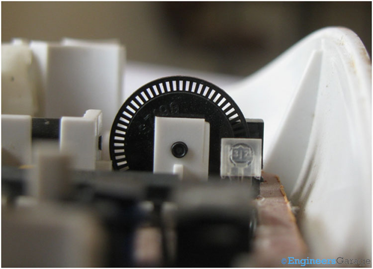
Fig. 6: Image Indicating the Disks of Sensor Mechanism of Mouse
The disks attached with the rollers are specially shaped with equidistant holes in their circumference as shown in the image above. They are responsible for converting the mechanical motion into electrical pulses for further usage by the computer.
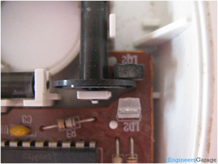
Fig. 7: Image Showing the Positioning of LED, Roller Disks, and Infrared Sensor
The disc of the rollers is placed between an infrared LED and an infrared sensor as shown in the above image. The disc is positioned such that the holes on the circumference either allow or block the infrared rays from the LED to fall on the sensor. The sensor therefore gives the output as sequence of electrical pulses.
Semiconductor Chip/IC
![]()
Fig. 8: Image Showing the Semiconductor Chip/IC
The chip shown in the middle of the above picture is an on board processor which collects the input from all the sensors and the mini switches. It processes the signals and sends them to the computer.
Ball & Scroll Mechanism

Fig. 9: Image Showing the Ball Mechanism
A spring is used to hold the ball in the proper position. Whenever the ball slips from its regular position a shaft attached with the spring brings the ball back in the right position.
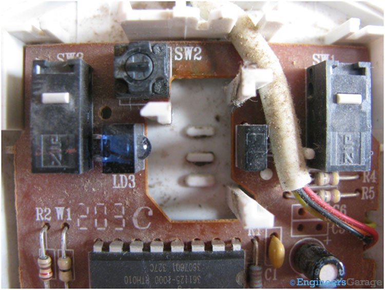
Fig. 10: Scrolling Wheel of Computer Ball Mouse
This wheel is used for scrolling the mouse on the screen. The working of wheel is similar to the rollers with a pair of infrared LED and sensor placed on opposite side of the wheel. A small steel rod shown in the left image is used to hold the wheel in the right position. The internal structure of the wheel has small rectangular bumps, so when the wheel rotates and the steel rod strikes these bumps they produce a small sound which we hear when we scroll the mouse.
Click Mechanism

Fig. 11: Scrolling Wheel of Computer Ball Mouse
Miniature size switches are used as left, right and middle click as shown in the image. The design of the top half is in such a way that it presses these switches along with the mechanical moving parts corresponding to each click.
Filed Under: Insight


Questions related to this article?
👉Ask and discuss on Electro-Tech-Online.com and EDAboard.com forums.
Tell Us What You Think!!
You must be logged in to post a comment.