A transformer is an electrical device that works on the principle of Faraday’s law of electromagnetism and is used to step up or down the input voltage. Faraday’s law predicts how a magnetic field will interact with an electric circuit to produce an electromotive force. It explains the process of electromagnetic induction, which is the basis for many electrical devices and technologies.
Several types of transformers are available with unique features:
- Current transformer — reduces or multiplies an alternating current
- Power transformer – transmits electrical power from one circuit to another without changing the frequency
- Potential transformer – converts voltage from a higher value to a lower value
- Pulse transformer – designed to transmit electrical pulses or high-frequency signals with minimal distortion
- RF transformer – transfers energy from one circuit to another by electromagnetic induction
- Audio transformer — transmits and modifies input electromagnetic signals into output signals via inductive coupling
In this article, we’ll cover current transformers, which reduce high-voltage currents to a lower value, often providing a convenient way of safely monitoring a device’s electrical current. These transformers can provide galvanic isolation in current-sensing devices. Examples include a switched-mode power supply (SMPS), motor control, or electronic lightning ballasts.
Now that we know the basics of how a current transformer works, let’s take a look inside this small device.

A typical current transformer.
The marking on a current transformer is important, stating the number of turns in its secondary coil. Manufacturers use unique formats for marking each device. For example, the above transformer has 54XXXC, wherein three digits replace the X’s, representing the turns in the secondary coil. So, 54050C would mean that the secondary coil has 50 turns.
The packaging

A view of the transformer’s packaging.
This transformer has a polymer housing made of a material known as UL94 V-0, which complies with the RoHS standards. RoHS stands for Restriction of Hazardous Substances, and compliance means that an independent authority has tested a product for certain banned substances.
UL 94 refers to a plastics flammability standard released by the Underwriters Laboratories. The standard classifies plastics, typically used in electronic devices, according to how they burn in various orientations.
The last two alphanumeric represents a flame rating. So, V-0 means the flames will dissipate within 10 seconds max, without burning the material.
The windings and pin structure
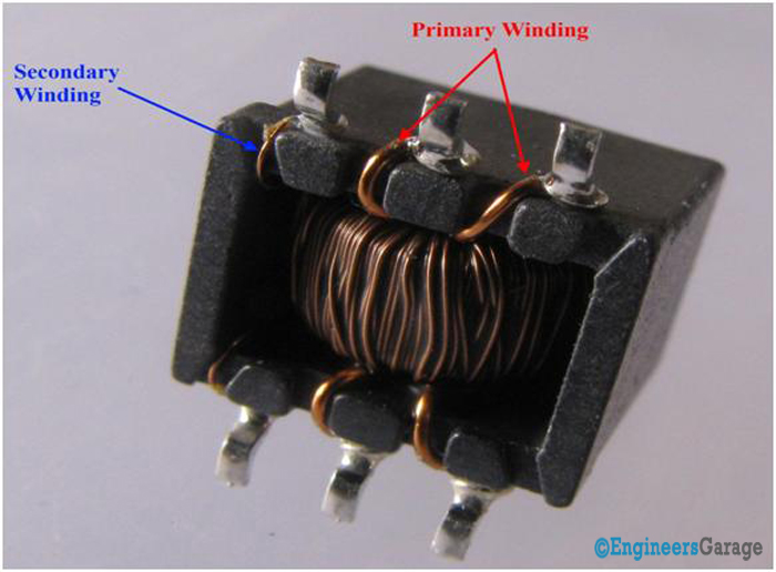
The windings inside a current transformer.
Copper wires are used as current-carrying conductors on the underside of this current transformer. There are six terminals, of which two are connected with the secondary winding and four with the primary winding.
The primary winding has a larger cross-section area because a wire’s resistance is inversely proportional to its cross-sectional area. The input current for the transformer must be more than the secondary one. Therefore, the secondary coils have a lower cross-sectional area to minimize the magnetic flux density.
There are two primary coils in this device with a 1:1 ratio, which improves the safe current capacity of the transformer.
The pin structure

The structure of the current transformer.
This current transformer is a six-pin device. The pins serve as input and output terminals. A circular groove at the bottom left corner of the transformer identifies the pin structure.
The primary windings are connected to pins 1 and 6, then 2 and 5, and then 3 and 4 of the secondary winding. The turn ratio of the device is 1:1:200, where 200 is the secondary coil turn ratio.
The internal structure

The internal structure of the current transformer’s wiring.
The transformer’s polymer housing was carefully cut open to view how the copper windings overlap. The windings are placed concentrically to reduce flux leakage in the transformer.

The primary windings in a current transformer.
Core and coils
There are two primary single-turn windings, which overlap the secondary winding. Insulators made from varnish or enamel separate the primary and secondary winding. The transformer also has insulation inside to prevent the conductors from shorting.

The core and coils of the current transformer.
After removing some of the copper wires, it’s possible to see “the core” of the transformer. This is a toroidal design, wherein the conductor tightly surrounds the center core without an air gap.
The ferrite toroidal core transfers energy through a magnetic field. It’s used to reduce losses in high frequencies.

The ferrite toroidal core inside the current transformer.
Filed Under: Insight, Tech Articles

Questions related to this article?
👉Ask and discuss on Electro-Tech-Online.com and EDAboard.com forums.
Tell Us What You Think!!
You must be logged in to post a comment.