Engineers Garage

  • Electronics Projects and Tutorials
    • Electronic Projects
      • Arduino Projects
      • AVR
      • Raspberry pi
      • ESP8266
      • BeagleBone
      • 8051 Microcontroller
      • ARM
      • PIC Microcontroller
      • STM32
    • Tutorials
      • Audio Electronics
      • Battery Management
      • Brainwave
      • Electric Vehicles
      • EMI/EMC/RFI
      • Hardware Filters
      • IoT tutorials
      • Power Tutorials
      • Python
      • Sensors
      • USB
      • VHDL
    • Circuit Design
    • Project Videos
    • Components
  • Articles
    • Tech Articles
    • Insight
    • Invention Stories
    • How to
    • What Is
  • News
    • Electronic Product News
    • Business News
    • Company/Start-up News
    • DIY Reviews
    • Guest Post
  • Forums
    • EDABoard.com
    • Electro-Tech-Online
    • EG Forum Archive
  • DigiKey Store
    • Cables, Wires
    • Connectors, Interconnect
    • Discrete
    • Electromechanical
    • Embedded Computers
    • Enclosures, Hardware, Office
    • Integrated Circuits (ICs)
    • Isolators
    • LED/Optoelectronics
    • Passive
    • Power, Circuit Protection
    • Programmers
    • RF, Wireless
    • Semiconductors
    • Sensors, Transducers
    • Test Products
    • Tools
  • Learn
    • eBooks/Tech Tips
    • Design Guides
    • Learning Center
    • Tech Toolboxes
    • Webinars & Digital Events
  • Resources
    • Digital Issues
    • EE Training Days
    • LEAP Awards
    • Podcasts
    • Webinars / Digital Events
    • White Papers
    • Engineering Diversity & Inclusion
    • DesignFast
  • Guest Post Guidelines
  • Advertise
  • Subscribe

Insight – How Micro Switch Works

By Ashutosh Bhatt November 5, 2012

Image of Micro-Switch
 
Fig. 1: Image of Micro-Switch
 
A micro switch, also known as miniature snap action switch, is a type of momentary contact switch used widely in automotive, industrial and medical instruments as sensor. The switch is termed as “micro” on the name of the company who first started manufacturing it commercially.
The actuator of these switches often has a hinged wheel placed above a push button. This switch is widely used in control system applications such as a door interlock, safety switches in elevators, vending machines etc. Having a diverse range of engineering applications, micro switches are available in various switch configurations, housing materials, actuator styles etc.
But what makes these switches to be called as “snap action” switches? How the momentary contact is managed by the switch? Is there a combination of spring or thin plastic fibers that allow such motion? Continue reading to reveal all the answers.
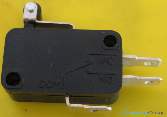
 
Image of SPDT Micro Switch.jpg
 
Fig. 2: Image of SPDT Micro Switch
 
A conventional SPDT micro switch is shown in the image above. It is a blunt edged rectangular structure having three output contact strips denoting common (ground), open and closed state respectively.
Two diagonally opposite holes are dug in to provide easy mounting of the switch on surface. Similarly, holes at the terminals of output contact strips allow easy soldering with the wires. The plastic box can be made of polyester or phenolic plastic products.

Actuator Assembly

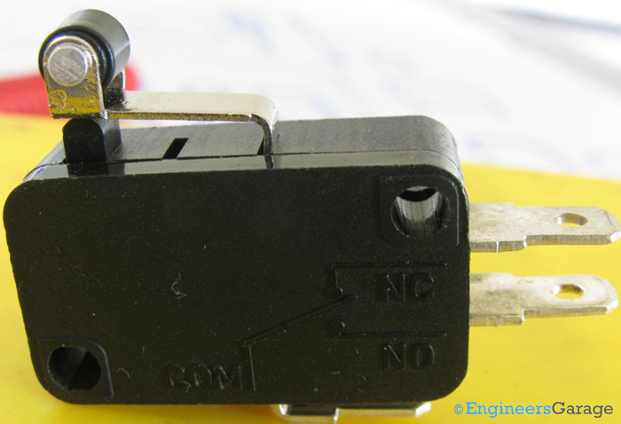
Rest State of Actuator.jpg
 
Fig. 3: Rest State of Actuator
 
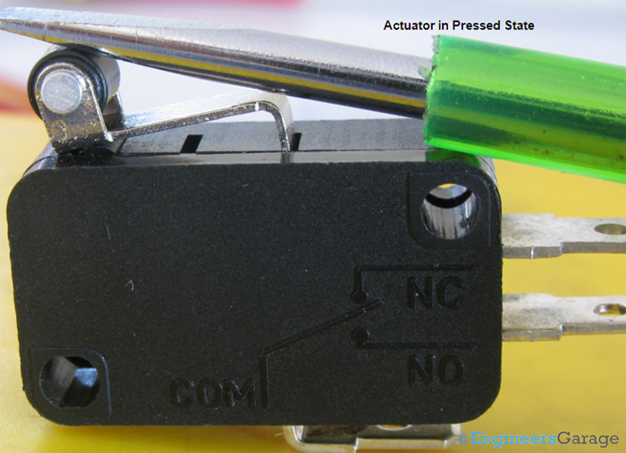
Actuator in Pressed State
 
Fig. 4: Actuator in Pressed State
 
Actuator assembly of the switch is a combination of a hinged wheel and a push button. The images above show the actuator assembly and its movement when switching state is changed.
Movement of Actuator: For this switch as the rest state of this switch is the normally connected position (NC) while the active state, i.e. the state when the actuator is pressed, is the normally open (NO) state of the switch.

ON and OFF State
Internal Assembly of Normally Connected State of Switch
 
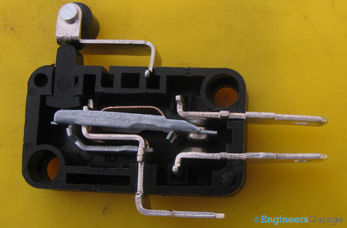
Fig. 5: Internal Assembly of Normally Connected State of Switch
 
The image above shows the NC or Normally Connected state of the switch. Here, the actuator is not pressed and hence, all other parts stay in their default rest state.
Let’s find out the internal assembly of the switch that responds to the actuator force and changes the state of the switch.
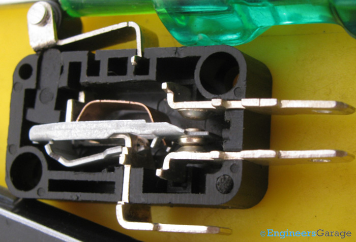
 
Internal Assembly of Active State of Switch
 
Fig. 6: Internal Assembly of Active State of Switch
 
The active state of the switch, i.e., when the actuator is pressed can be seen above. In this image, the movement of the different parts is shown when the actuator is pressed.

Internal Structure
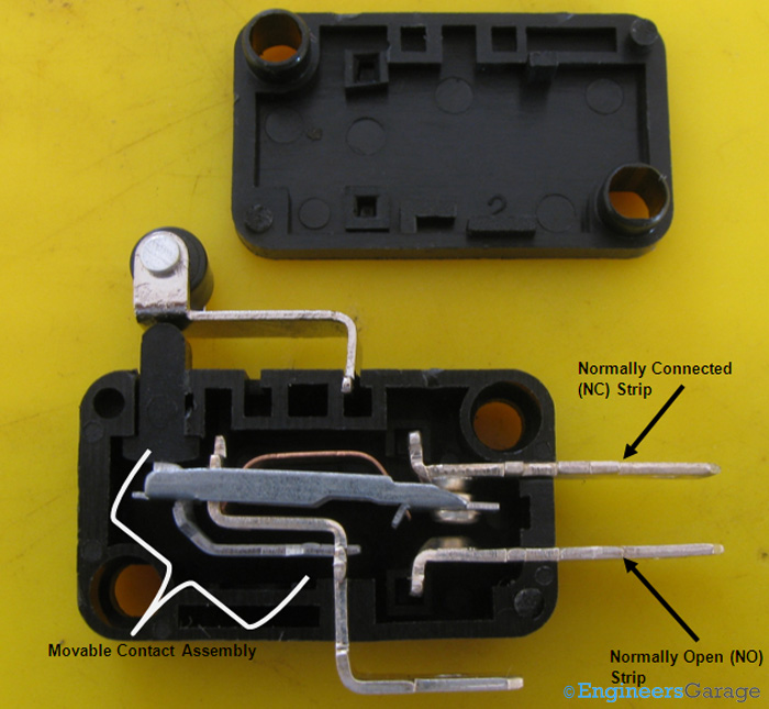
Assembly of Internal Structure of Switch
 
Fig. 7: Assembly of Internal Structure of Switch
 
Internal Structure Assembly: On opening the plastic casing of the switch, the different parts of the internal structure of the switch can be seen. It is a simple assembly, comprising of:
1.                  Two stationary contacts for NC and NO position.
2.                  One movable contact assembly.

Movable Contact Assembly
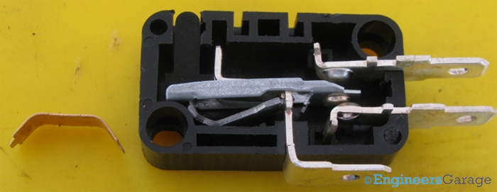
Lever Assembly in Pressed State of Actuator
 
Fig. 8: Lever Assembly in Pressed State of Actuator
 
Tensile Metal Strip: The part taken out from the movable contact assembly is a metallic strip shaped like an inverted “U” that is stretched from its sides. This small tensile strip gives the restraining force to the movable contact, bringing it back to its rest state after force from actuator is removed. Working like a spring, this strip is responsible for the “snap” action of the micro switch.
The image above shows the actuator in the pressed state even there is no force upon it. This is due to no resilient force acting on the movable contact to bring it up and push the actuator to its rest state.
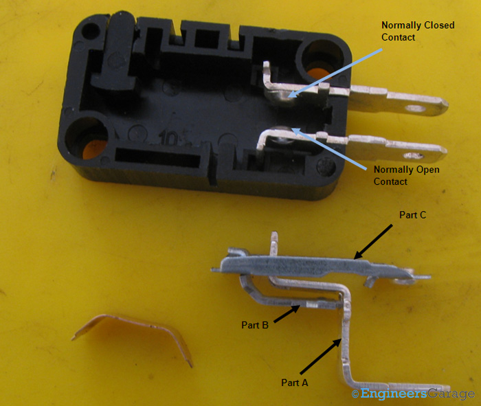
 
Dissected Parts of Internal Assembly
 
Fig. 9: Dissected Parts of Internal Assembly
 
Parts clung to Ground Contact Strip: The rest of the mechanical assembly of the movable contact has been taken out from the plastic base in the image above. The parts are:
1.                  Contact strip serving as common (ground). (Labeled as part A)
2.                  A bent strip placed beneath the actuator assembly.(Labeled as part B)
3.                  A dive board shaped movable contact. (Labeled as part C)

Common Contact Strip

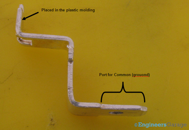
Common Contact Strip: The image above shows stair shaped ground contact strip which also holds the rest of the parts of the movable contact assembly. The upper part of the contact is fixed between the moldings on the plastic base while lower part emerges out as a contact strip.
 
Stair-Shaped Ground Contact Strip
 
Fig. 10: Stair-Shaped Ground Contact Strip
 
A number of sections have been cut on the plate to allow other parts of the movable contact to cling on.
Bent Strip placed beneath actuator
 
Bent Strip that is Placed Beneath the Actuator Assembly
 
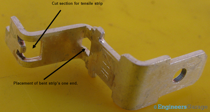
Fig. 11: Bent Strip that is Placed Beneath the Actuator Assembly
 
Bent Strip: The bent strip placed beneath the actuator assembly has been shown in the image above. One end of this strip is placed inside a cut section of the ground contact strip and the other end of this strip is placed in a cut section of the movable contact.
The task of this strip is to transfer the force exerted by the actuator to the movable contact which then moves and make connections with the NO contact of the switch.
As soon as the force from actuator is released, the movable contact comes at rest state due to resilient force of the tensile strip and this strip forces the actuator back to its rest state.

Movable Contact
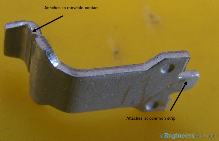
Image showing the Shape of Actuator
 
Fig. 12: Image showing the Shape of Actuator
 
Movable Contacts: The images above show the movable contact from both of its sides and the bulge on each. It has to establish connections with both the output contacts and facilitating it are the bulges on both sides. 

Filed Under: Insight
Tagged With: actuator, contact strip, micro switch, switch
 

Next Article

← Previous Article
Next Article →

Questions related to this article?
👉Ask and discuss on EDAboard.com and Electro-Tech-Online.com forums.


Tell Us What You Think!! Cancel reply

You must be logged in to post a comment.

EE TECH TOOLBOX

“ee
Tech Toolbox: Internet of Things
Explore practical strategies for minimizing attack surfaces, managing memory efficiently, and securing firmware. Download now to ensure your IoT implementations remain secure, efficient, and future-ready.

EE Learning Center

EE Learning Center
“engineers
EXPAND YOUR KNOWLEDGE AND STAY CONNECTED
Get the latest info on technologies, tools and strategies for EE professionals.

HAVE A QUESTION?

Have a technical question about an article or other engineering questions? Check out our engineering forums EDABoard.com and Electro-Tech-Online.com where you can get those questions asked and answered by your peers!


RSS EDABOARD.com Discussions

  • Core loss in output inductor of 500W Two Transistor forward?
  • GanFet power switch starts burning after 20 sec
  • Colpitts oscillator
  • problem identifying pin purpose on PMA5-83-2WC+ amplifier
  • Voltage Regulator Sizing Question

RSS Electro-Tech-Online.com Discussions

  • LED circuit for 1/6 scale diorama
  • Electronic board faulty?!?
  • Can I use this charger in every country?
  • using a RTC in SF basic
  • An Update On Tarrifs

Featured – Designing of Audio Amplifiers part 9 series

  • Basics of Audio Amplifier – 1/9
  • Designing 250 Milli Watt Audio Power Amplifier – 2/9
  • Designing 1 Watt Audio Power Amplifier – 3/9
  • Designing a Bass Boost Amplifier – 4/9
  • Designing a 6 Watt Car Audio Amplifier – 5/9
  • Design a low power amplifier for headphones- 6/9

Recent Articles

  • Fischer connector system adds ratchet locking system designed for 300g shock resistance
  • Littelfuse introduces tactile switch with enhanced bracket peg design for mounting strength
  • Infineon releases GaN switch with monolithic bidirectional design
  • Sienna Semiconductor data converters feature sample rates from 20 to 250 Msps
  • Delta’s 5,500 W power supplies achieve 97.5% energy efficiency for AI servers

EE ENGINEERING TRAINING DAYS

engineering

Submit a Guest Post

submit a guest post
Engineers Garage
  • Analog IC TIps
  • Connector Tips
  • Battery Power Tips
  • DesignFast
  • EDABoard Forums
  • EE World Online
  • Electro-Tech-Online Forums
  • EV Engineering
  • Microcontroller Tips
  • Power Electronic Tips
  • Sensor Tips
  • Test and Measurement Tips
  • 5G Technology World
  • Subscribe to our newsletter
  • About Us
  • Contact Us
  • Advertise

Copyright © 2025 WTWH Media LLC. All Rights Reserved. The material on this site may not be reproduced, distributed, transmitted, cached or otherwise used, except with the prior written permission of WTWH Media
Privacy Policy

Search Engineers Garage

  • Electronics Projects and Tutorials
    • Electronic Projects
      • Arduino Projects
      • AVR
      • Raspberry pi
      • ESP8266
      • BeagleBone
      • 8051 Microcontroller
      • ARM
      • PIC Microcontroller
      • STM32
    • Tutorials
      • Audio Electronics
      • Battery Management
      • Brainwave
      • Electric Vehicles
      • EMI/EMC/RFI
      • Hardware Filters
      • IoT tutorials
      • Power Tutorials
      • Python
      • Sensors
      • USB
      • VHDL
    • Circuit Design
    • Project Videos
    • Components
  • Articles
    • Tech Articles
    • Insight
    • Invention Stories
    • How to
    • What Is
  • News
    • Electronic Product News
    • Business News
    • Company/Start-up News
    • DIY Reviews
    • Guest Post
  • Forums
    • EDABoard.com
    • Electro-Tech-Online
    • EG Forum Archive
  • DigiKey Store
    • Cables, Wires
    • Connectors, Interconnect
    • Discrete
    • Electromechanical
    • Embedded Computers
    • Enclosures, Hardware, Office
    • Integrated Circuits (ICs)
    • Isolators
    • LED/Optoelectronics
    • Passive
    • Power, Circuit Protection
    • Programmers
    • RF, Wireless
    • Semiconductors
    • Sensors, Transducers
    • Test Products
    • Tools
  • Learn
    • eBooks/Tech Tips
    • Design Guides
    • Learning Center
    • Tech Toolboxes
    • Webinars & Digital Events
  • Resources
    • Digital Issues
    • EE Training Days
    • LEAP Awards
    • Podcasts
    • Webinars / Digital Events
    • White Papers
    • Engineering Diversity & Inclusion
    • DesignFast
  • Guest Post Guidelines
  • Advertise
  • Subscribe