Engineers Garage

  • Projects and Tutorials
    • Electronic Projects
      • 8051
      • Arduino
      • ARM
      • AVR
      • PIC
      • Raspberry pi
      • STM32
    • Tutorials
    • Circuit Design
    • Project Videos
    • Components
  • Articles
    • Tech Articles
    • Insight
    • Invention Stories
    • How to
    • What Is
  • News
    • Electronic Products News
    • DIY Reviews
    • Guest Post
  • Forums
    • EDABoard.com
    • Electro-Tech-Online
    • EG Forum Archive
  • Digi-Key Store
    • Cables, Wires
    • Connectors, Interconnect
    • Discrete
    • Electromechanical
    • Embedded Computers
    • Enclosures, Hardware, Office
    • Integrated Circuits (ICs)
    • Isolators
    • LED/Optoelectronics
    • Passive
    • Power, Circuit Protection
    • Programmers
    • RF, Wireless
    • Semiconductors
    • Sensors, Transducers
    • Test Products
    • Tools
  • EE Resources
    • DesignFast
    • LEAP Awards
    • Oscilloscope Product Finder
    • White Papers
    • Webinars
  • EE Learning Center
    • Design Guides
      • WiFi & the IOT Design Guide
      • Microcontrollers Design Guide
      • State of the Art Inductors Design Guide
  • Women in Engineering

Insight – How Reed Switch works

By Ashutosh Bhatt

Magnets have a natural tendency to attract many things. Though not perceived as a real force, but it does attract human attention when a force acting invisibly draws things to itself. By harnessing this power, humans have made wonderful inventions like the electromagnet and discover lossless conduction phenomenon like superconductivity. Among these many inventions, was the application of magnetism to switch from ON state to OFF and vice-versa in precision devices. One such switching device, which works not by the principles of electricity, but magnetism, is the Reed Switch.

Reed switches work like an electromechanical relay switch, while the latter conducts current, the former conducts magnetic flux which is the quantitative measurement of magnetic field on a surface. First Invented by Bell Laboratories, reed switches today have a length of just a few millimeters and are used in numerous applications that range from a simple coffee maker to rain gauge, and satellite TV positioning. Let’s have a look on how this unsophisticated looking device makes a difference.
 
Image of a reed switch
 
Fig. 1: Image of a Reed Switch

Structure

Shown in the image below is a Single Pole Single Throw (SPST) Normally Open Switch. One of the most common types, it is a simple switch that connects two terminals (SPST). When not in use, the switch is open and does not conduct (Normally Open).
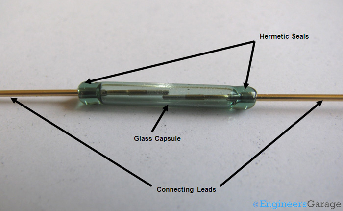
The structure of reed switch is quite clear right from the first sight. As shown in the image below, it is an assembly of connecting leads and a glass capsule. The glass capsule is hermetically (air tight) sealed It is achieved by partially annealing the capsule after the reed switch is made. Reeds also undergo the process of annealing like the glass capsule so that iron-nickel based ferromagnetic material does not retain any magnetism after the magnetic field is taken off. Making the capsule air tight ensures that switch is least affected by variable ambient temperature and pressure conditions.The process of sealing is usually carried out at elevated temperatures so that reed switch does not break down at high voltages like 240V.
 
Close Look of Reed Switch Structure
 
Fig. 2: Close Look of Reed Switch Structure
 
Inside the glass capsule, the leads are soldered to a ferromagnetic material, usually nickel-iron. The glass capsule protects the ferromagnetic parts from corroding. The empty space inside the glass capsule is filled by inert gases such as nitrogen so that the ferromagnetic materials don’t corrode with time and switch is able to handle high voltages. In the switches that work at high voltages, vacuum is created inside the glass capsule so that no voltage is induced that disturbs switching mechanism. Any unwanted stray voltage signal can cause variable outputs especially at lower temperatures and when working at high voltage, electrical breakdown of the air around the switch can disrupt normal switching due to loss of magnetising properties of the reed switch.Materials when heated beyond a critical temperature (called Curie temperature) lose their property of magnetism. The iron-nickel parts are soft and are sputtered with very hard and less reactive metals like Rhodium or Ruthenium to prevent fragments of reeds breaking out from their parent reed and sticking on to the other reed. Coating with hard material ensures that the switch responds instantly and also increases the longevity of the switch. Any material that makes regular contact with other material gradually deteriorates due to friction and scratching. Such problems can lead to loss of material through cold welding. This wear and tear is opposed by its inherent property called “wear-resistance.” Rhodium and Ruthenium have a high wear resistance and they also maintain metal’s property of responding to current. The contact areas overlap each other but have a little gap and do not touch until there is a magnetic field above the threshold value. It is the contact of these overlapping areas that allows the magnetic flux to pass through the switch.
The connecting leads are plated with Copper so that higher amount of currents can be handled as well corrosion protection is achieved.
 
 Image Showing Contact Area of Copper Connecting Leads
 
Fig. 3: Image Showing Contact Area of Copper Connecting Leads

The Reed

The name “Reed” is derived from a slender and tall species of grass which is known by the same name. The ferromagnetic material along with the contact area resembles a slender ‘reed’ grass structure with its flattened end.  As the name suggests, the reed is the heart of the switch and ideally is sensitive to slightest of change in the magnetic field.  The iron-nickel part is joined to the connecting leads through soldering. Tin is plated over the iron-nickel leads in order to facilitate easy and long lasting soldering process. The reeds have reasonable elasticity with the intention that they can bend and connect when magnetic field is applied and get restored when the field is withdrawn. The magnetic field has to be strong enough so that it can cross the threshold of restoring.
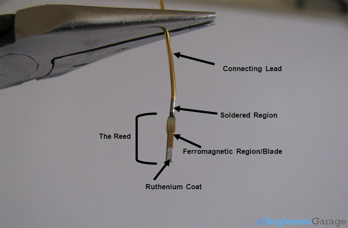
The reed shown in the image below has one end in a flattened rectangular shape where Rhodium, Ruthenium coat has been done. The flattened end can have a circular or any other polygonal shape as per the application of the switch.
 
Specific Parts of
 
Fig. 4: Specific Parts of “reed” in Reed Switch

Working

Working:
In order to make the Reed switch work, it can be:
1.   Placed parallel to a magnet.
2.   Placed between magnetic coils.
 
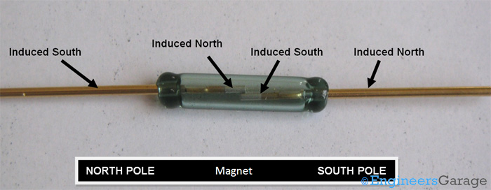
When placed parallel to a magnet, the lead and the reed turn into a temporary magnet as it is a ferromagnetic material.
 
Functional Integrity of Reed Switch
 
Fig. 5: Functional Integrity of Reed Switch
 
A magnet has two poles – North Pole and South Pole. Lines of force (flux lines) can be considered to be emanating from the North Pole, moving in a circular path and entering the magnet back at the South Pole completing a closed loop. Inside the magnet, these lines are directed from North to South direction while outside, the opposite direction persists.  This means that an isolated North Pole or an isolated South Pole cannot exist and the flux lines from the North Pole passing through space must reach the South Pole.
 
These imaginary lines of force represent a physical force field where the influence of the magnet can be felt. If some suitable material like a ferromagnetic piece is kept in this region, it will experience a force in a direction the flux lines point. The influence of these magnetic flux lines entering this material is such that the North Pole induces an opposite pole, i.e. the South Pole on the side of that material nearer to it and consequently a North Pole is formed at the farther side. Thus, the material which was placed in the field of this magnet starts acting like a magnet itself. How strong this newly formed temporary magnet is, depends on how easily it allows the lines to pass through it, or simply speaking, how susceptible it is to magnetization. Ferroelectric materials form a special class of material that are very susceptible to magnetization and hence find extensive use in such applications.
 
Similar conditions are met for the other reed, which is relatively closer to the South Pole of the magnet. In addition to it, the newly formed temporary magnet on the adjacent reed facilitates the formation of a South Pole on the side facing the first reed, thus creating an attractive force between the two reeds. When this attractive force exceeds the restoring elastic force of the reeds, the two connect.
 
Reed Swith in Open State
 
Fig. 6: Reed Swith in Open State
 
Reed Switch in Closed State that Enhances its Magnetic Functionality
 
Fig. 7: Reed Switch in Closed State that Enhances its Magnetic Functionality
 
In the case when the switch is placed between current carrying coils which act like an electromagnet, the switch gets magnetized and behaves exactly like a magnet does. As a result, the reeds get polarized just like it did in the case of a permanent magnet to form opposite poles and the ferromagnetic blades get connected.

Reed switches can work for low as well as high voltage applications; however, they have a higher lifetime when they work for lower voltages. They are not affected by power failures and are neither affected by harsh ambient conditions of dust, humidity and temperature extremes. Being operated only under magnetic influence, they don’t bear any stray charges thus avoiding the electrostatic discharge (ESD) problem. Once mounted on a circuit, reed switches don’t require any maintenance and can work efficiently over a wide range of voltages. 


Filed Under: Insight
Tagged With: reed, reed switch, switch
 

Questions related to this article?
👉Ask and discuss on Electro-Tech-Online.com and EDAboard.com forums.


Tell Us What You Think!! Cancel reply

You must be logged in to post a comment.

HAVE A QUESTION?

Have a technical question about an article or other engineering questions? Check out our engineering forums EDABoard.com and Electro-Tech-Online.com where you can get those questions asked and answered by your peers!


Featured Tutorials

  • PS2 Keyboard To Store Text In SD Card Using Arduino Circuit Setup On Breadboard
    How To Use PS2 Keyboard To Store Text In SD Card Using Arduino- (Part 42/49)
  • Wireless Path Tracking System Using Mouse, XBee And Arduino Circuit Setup On Breadboard
    How To Make A Wireless Path Tracking System Using Mouse, XBee And Arduino- (Part 43/49)
  • How to Make a Wireless Keyboard Using Xbee with Arduino- (Part 44/49)
  • Making Phone Call From GSM Module Using Arduino Circuit Setup On Breadboard
    How to Make Phonecall From GSM Module Using Arduino- (Part 45/49)
  • How to Make a Call using Keyboard, GSM Module and Arduino
    How To Make A Call Using Keyboard, GSM Module And Arduino- (Part 46/49)
  • Receiving SMS Using GSM Module With Arduino Prototype
    How to Receive SMS Using GSM Module with Arduino- (Part 47/49)

Stay Up To Date

Newsletter Signup

Sign up and receive our weekly newsletter for latest Tech articles, Electronics Projects, Tutorial series and other insightful tech content.

EE Training Center Classrooms

EE Classrooms

Recent Articles

  • What is a low power design?
  • Renesas partners with Tata to accelerate progress in advanced electronics
  • STMicroelectronics’ new touchscreen controller for smartphones enables longer runtime
  • Samsung unveils ISOCELL image sensor with industry’s smallest 0.56μm pixel
  • Renesas and Cyberon to deliver integrated voice-user interface solutions

Most Popular

5G 555 timer circuit 8051 ai Arduino atmega16 automotive avr bluetooth dc motor display Electronic Part Electronic Parts Fujitsu ic infineontechnologies integratedcircuit Intel IoT ir lcd led maximintegratedproducts microchip microchiptechnology Microchip Technology microcontroller microcontrollers mosfet motor powermanagement Raspberry Pi remote renesaselectronics renesaselectronicscorporation Research samsung semiconductor sensor software STMicroelectronics switch Technology vishayintertechnology wireless

RSS EDABOARD.com Discussions

  • Atrduino IDE ompilation Error
  • Cadence Layout (LVS error in bulk connections)
  • FPGA LVDS with separate clock
  • Limits of duty cycle for ICM7555 IC?
  • 12V 5A needed

RSS Electro-Tech-Online.com Discussions

  • Lighting a .010 green fiber optic with led
  • Bridge purpose in connecting the two functional circuit
  • ICM7555 IC duty cycle limit at high frequency?
  • How to quickly estimate lead acid battery capacity ?
  • intro to PI
Engineers Garage
  • Analog IC TIps
  • Connector Tips
  • DesignFast
  • EDABoard Forums
  • EE World Online
  • Electro-Tech-Online Forums
  • Microcontroller Tips
  • Power Electronic Tips
  • Sensor Tips
  • Test and Measurement Tips
  • 5G Technology World
  • About Us
  • Contact Us
  • Advertise

Copyright © 2022 WTWH Media LLC. All Rights Reserved. The material on this site may not be reproduced, distributed, transmitted, cached or otherwise used, except with the prior written permission of WTWH Media
Privacy Policy | Advertising | About Us

Search Engineers Garage

  • Projects and Tutorials
    • Electronic Projects
      • 8051
      • Arduino
      • ARM
      • AVR
      • PIC
      • Raspberry pi
      • STM32
    • Tutorials
    • Circuit Design
    • Project Videos
    • Components
  • Articles
    • Tech Articles
    • Insight
    • Invention Stories
    • How to
    • What Is
  • News
    • Electronic Products News
    • DIY Reviews
    • Guest Post
  • Forums
    • EDABoard.com
    • Electro-Tech-Online
    • EG Forum Archive
  • Digi-Key Store
    • Cables, Wires
    • Connectors, Interconnect
    • Discrete
    • Electromechanical
    • Embedded Computers
    • Enclosures, Hardware, Office
    • Integrated Circuits (ICs)
    • Isolators
    • LED/Optoelectronics
    • Passive
    • Power, Circuit Protection
    • Programmers
    • RF, Wireless
    • Semiconductors
    • Sensors, Transducers
    • Test Products
    • Tools
  • EE Resources
    • DesignFast
    • LEAP Awards
    • Oscilloscope Product Finder
    • White Papers
    • Webinars
  • EE Learning Center
    • Design Guides
      • WiFi & the IOT Design Guide
      • Microcontrollers Design Guide
      • State of the Art Inductors Design Guide
  • Women in Engineering