We are accustomed to using transformers in voltage stepping applications and in providing isolation to output circuits from the loading and transient effects that affect the input. These transformers work fine in most of the scenarios we encounter in day to day life, like the mobile phone charger, DC Adapter, the Step Down transformer at the nearby electrical distribution pole etc. But, when it comes to applications where square, pulse-like waveforms are required, the conventional transformers output a distorted waveform.
Hence, for applications such as digital communications, camera flashes, radar systems and other fields where pulsed form of relatively high voltage is required, special type of transformers, ‘pulse transformers’ are required. Pulse Transformers are small in size and provide all the desirable qualities expected of the transformers designedto handle square pulses. Let us explore the structure of one such pulse transformer and try to find out how it stands apart from conventional transformers.
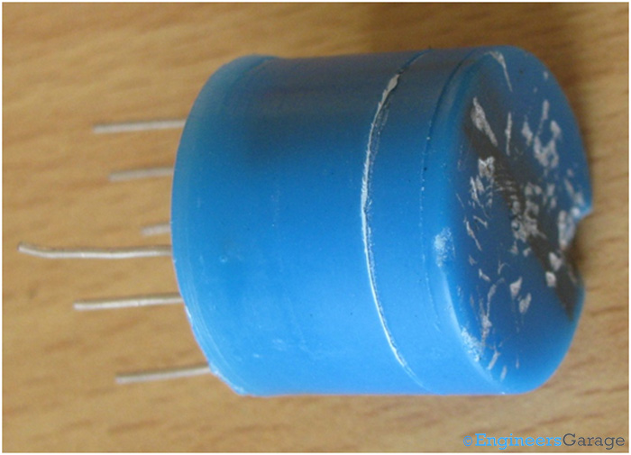
Fig. 1: A Standard Pulse Transformer
Outer Casing
OUTER CASING
Cased in a plastic shell, the transformer presented here has two secondary coils and one primary coil. The turn ratio is usually mentioned on the packaging of the transformer. In this case, it is ‘1:1:1’ as mentioned in the front portion of the transformer. Multiple numbers of secondary coils are often required in order to provide multiple output ports to the transformer.Depending on what the intended application is, a pulse transformer may have a 1:1 configuration as in a simple transformer for coupling input to a single output, a 1:1:1 configuration often used in firing 2 SCRs in inverse parallel configuration, or even a 1:1:1:1 configuration also known as a Flyback Transformer. The secondary windings are mutually isolated electrically to ensure minimum leakage inductance and other coupling side effects in between the secondary coils.
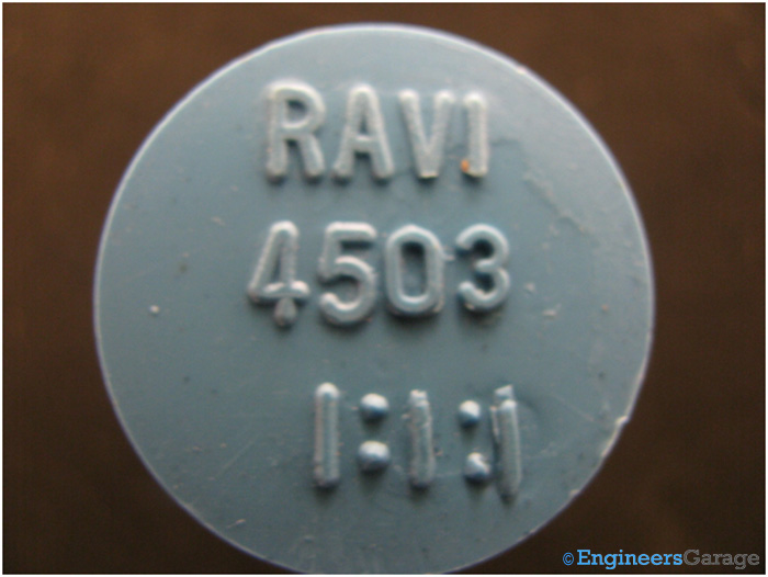
Fig. 2: Image Showing Outer Casing of A Pulse Transformer
A lateral view of the transformer gives an appearance of a miniature satellite to it as it has as 6 legs. Out of these 6 legs, 2 are connected to the primary while the other 4 represent the two pairs of secondary coils.
The shell firmly adheres to the transformer through a thick layer of epoxy resin, keeping the transformer safe from ambient influences and mechanical jerks. On removing the shell, this dense plastic packaging is revealed. It is a semi translucent layer hinting at its internal components. The epoxy layer also helps keep the legs in their positions firmly to minimize stray losses and random fluctuations across the output ports of the secondary coils due to shorting or coupling. Shown in the image below is the view of the transformer after the plastic casing is removed.
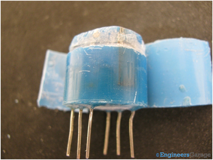
Fig. 3: Image Showing Lateral View of Pulse Transformer
The Transformer
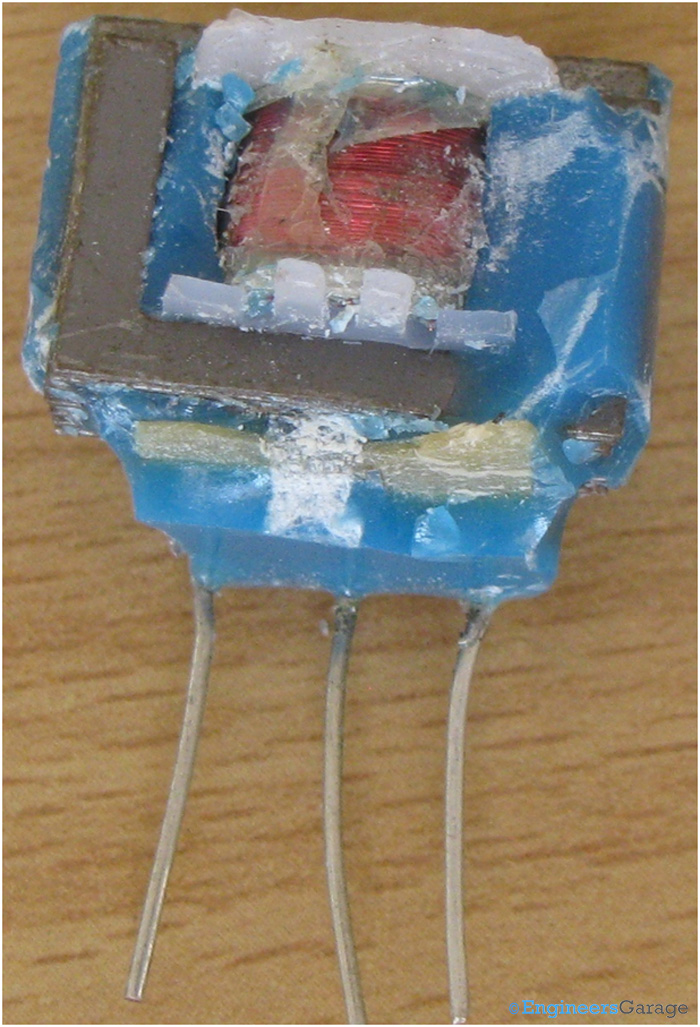
Fig. 4: Internal View of Pulse Transformer
Scraping off the epoxy resin from the transformer reveals the real transformer. We can see a glimpse of almost everything in the image above, the coils, the frame, legs, lamination and epoxy.
Constructional features
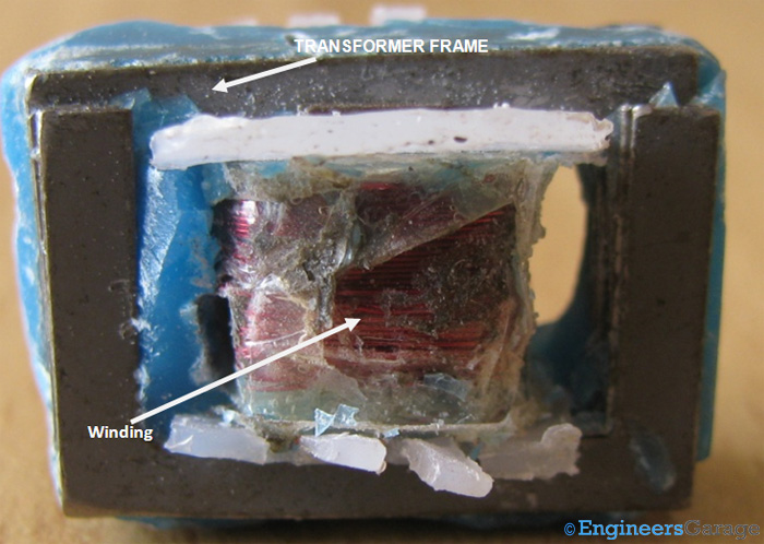
Fig. 5: Image Showing Constructional Features of Pulse Transformer
It is at this level those significant constructional dissimilarities between a conventional transformer and pulse transformer surface. The first and foremost difference is the way the way the coils are wound on the frame. Most conventional transformers utilize a ‘core type’ winding where the windings are on the outside while the frame is inside. Pulse transformers utilize a ‘shell type’ winding where the frame surrounds the windings. This type of construction has characteristics like reduced susceptibility to eddy current and flux leakage losses, higher voltage and short circuit handling capability. Shell based transformers are mechanically more strengthened than the core type transformers. The primary and secondary are coiled over each other, thus are not recognizable until the coils are cut. Each layer is separated from the other layer with a layer of insulator. Other winding designs are also possible like the windings being wound side by side in a pancake stack. When pulses are applied in the primary coil, a similar voltage is induced in the secondary coils due to magnetic coupling and mutual induction.
Another property desired of transformers used with square pulses is rapid and repeated magnetization-demagnetization cycles. The steeper the hysteresis loop, the better. Therefore, Pulse transformers need to have a rectangular hysteresis loop to meet such a requirement. Unlike analog signal transformers, there can be no middle state of magnetization in Pulse transformers. In order to fulfill this requirement, significant constructional improvements are incorporated in design. The number of turns in a pulse transformers are lesser than analog signal ones so that stray inductance losses are low. The capacitance between the primary and secondary is also lesser in pulse transformers.The material used in the frame must have high permeability with a large inductance value to allow rapid magnetization/demagnetization. This imposes a restriction on the use of common material like Silicon Steel, which is usually used in conventional analog transformers, being used in Pulse transformers. These properties make pulse transformer able enough to minimize the distortion losses while transmitting the input square waves.
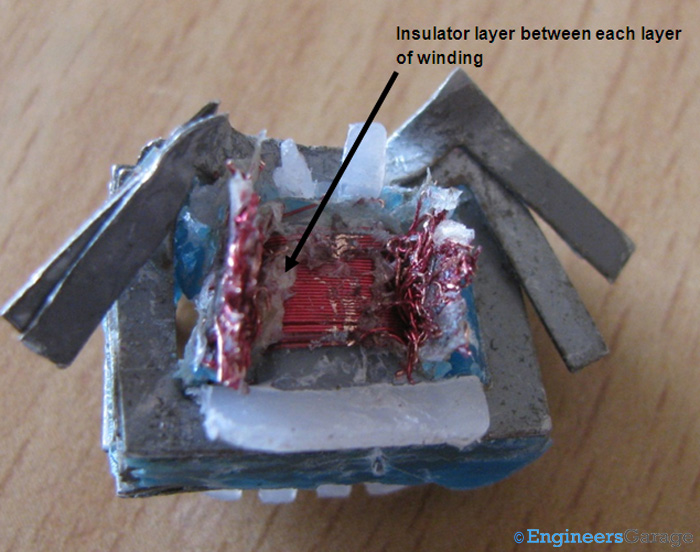
Fig. 6: Diagramatical Image Showing Various Layers of Pulse Transformer
For shell based transformers, the frame has a flattened ‘8’shape. This shape is achieved by stacking two ‘E’ shaped frames in mirror image symmetry. It is more easy to wind the coils on the central leg of an ‘E’ shaped frame as compared to the ‘8’ shaped frame, thus reducing the time taken to manufacture such transformers. Shown below is a stack of laminated frames (left) and a single frame structure (right)which is generally made of Permalloy or ferrite based µmetal.These materials have very high magnetic permeability and hence,high magnitudes of inductance.Every frame in this laminated structure is electrically insulated from the other by a layer of paint/oil to maximize surface area, thereby minimizing eddy current losses.
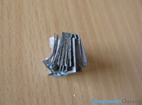
Fig. 7: Stack of Frames
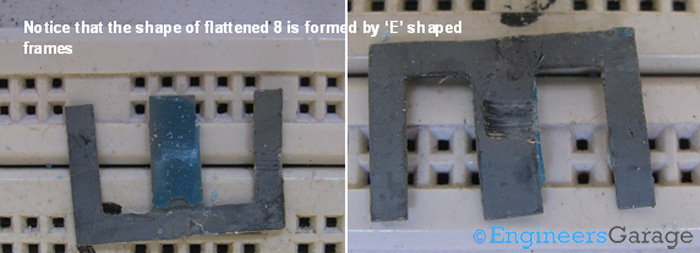
Fig. 8: Images Showing A Closer View of ‘E’ Shaped Frames
Terminal Connections
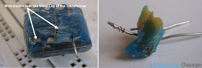
Fig. 9: Pictures Showing Closer View of Terminal Connections
The legs of the transformer are shown in the images above. They are placed over an insulator to prevent contact with the transformer frame and winding terminations are wound on them. To maximize connection integrity between the legs and the wire terminations, some segments of the wound wires are soldered to the legs as seen in the image above (right).
For any typical pulse transformer, output depends upon input from the source, number of turns, pulse duration and maximum voltage that it can handle. Pulse transformers of small power ratings are used in digital communications and logic circuits to couple “signals” while those with medium power ratings are used in applications such as camera flashes. Large power pulse transformer applications include firing of TRIACs and SCRs.Higher power handling versions are used in RADARs, particle accelerators etc.
Filed Under: Insight


Questions related to this article?
👉Ask and discuss on Electro-Tech-Online.com and EDAboard.com forums.
Tell Us What You Think!!
You must be logged in to post a comment.