Like other motors a Stepper motor also converts the electrical power into mechanical rotation. A stepper motor rotates in distinct steps where each step is a fraction of a full circle. Stepper motors are driven with pulses and one set of pulses can move the stepper motor by one step only.

Fig. 1: Image of Five-Wired Hybrid Stepper Motor
A five wired hybrid stepper motor is shown in the above image. The shaft is visible in the middle of the motor. The top and bottom mounting plates made up of aluminum with stator in between. The rotor shaft and wires are coming out.
Internal Structure

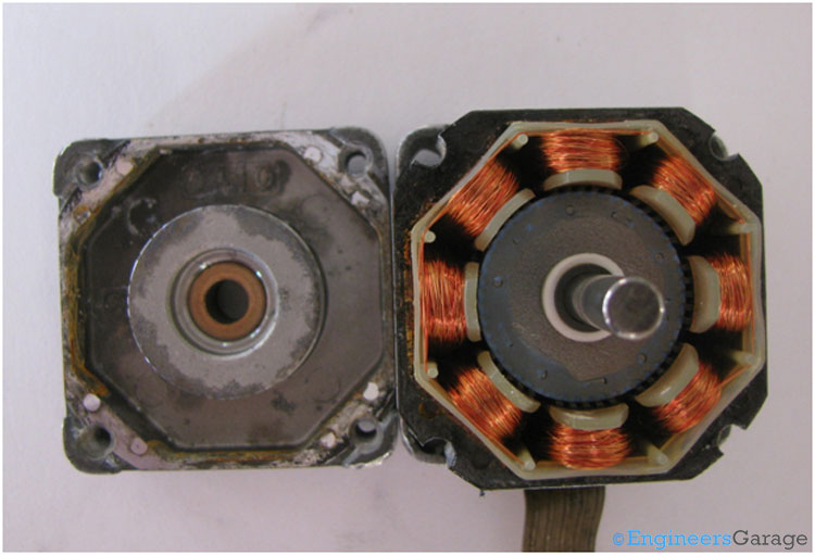
Fig. 2: Stepper Motor Parts—Rotor and Stator
A Stepper motor has a stator and a rotor. The rotor has a permanent magnet attached to it. The stator is made up of coils as shown in the above image.

Fig. 3: Sator Coil Layout
There are eight coils in this motor. Every coil in the motor behaves as an electromagnet when they are energized by electrical pulses.
PCB

Fig. 4: Image Showing PCB and Layout of Wire Connections
The PCB has five wires which are connected with the coils. Every pair of alternate coils is connected together.

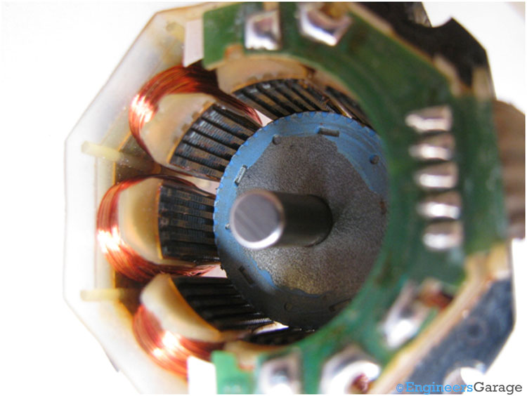
Fig. 5: Rotor and Stator Arrangement
The above image shows the rotor which is placed in the stator having a small air gap in between.
Rotor Contd.

Fig. 6: Image of Build-up of Rotor
The rotor is made up of a permanent magnets core with two soft iron discs with teeth on the periphery. The number of teeth decides the step angle of the motor. The teeth on the front disk form the permanent magnetic south poles whereas the teeth on the rear disk form the permanent magnet north poles. The overall structure looks like a pair of gears stick to each other. The alignment of the teeth is done in such a manner that the teeth on one disc are positioned between the space in the two consecutive teeth on the other disc and vice versa.
Stator

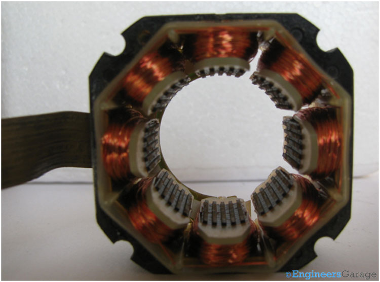
Fig. 7: Structure of Stator
Structure of the stator is shown in the above image. The stator also contains teeth which are electromagnetic in nature. Every tooth is surrounded by a coil. Depending on the polarity of the current supplied in the coil, the tooth can be made to behave like N or S poles. There are a total of eight teeth in the stator.

Fig. 8: Figure Indicating PCB and Wire set-up with Stator
PCB has five output wires – four wires each connected with two alternate coils and one for common wire.
Filed Under: Insight


Questions related to this article?
👉Ask and discuss on EDAboard.com and Electro-Tech-Online.com forums.
Tell Us What You Think!!
You must be logged in to post a comment.