This one is the best IR remote control because it nullifies all the drawbacks of all above remotes. Micro-controller is used on both the sides so transmitter as well as receiver both is programmable. Maximum 64 different functions can be utilized with this IRRCS. Some of the applications that I have implemented using this IRRCS are “IR DC Motor Speed control with digital display”, “IR stepper motor control with LCD display” and “Multi digit wireless password lock with LCD”. Let’s see some of its features.
Features:-
· Programmable, microcontroller (89C51) based remote control
· Maximum 64 keys in remote control so 64 different functions can be utilize
· Micro-controller(89C51) based receiving unit
· Multi functional, programmable receiving unit
· Application specific programming of micro-controller for industrial purpose
· It’s multi functional unit so can be attached to any application
· It can be used in industries to control/operate any application/device remotely
· It can be used in homes/offices to operate any appliance remotely like fan, bulb, air cooler, table lamp etc.
Probably you will be thinking what’s new in this system
What’s new?
In previous two IR remote controls there was a limit on maximum number of functions that can be utilized because number of keys in remote control is limited up to 8 or 10. This limit is completely violated here because maximum number of keys is now 64. So 64 different functions can be utilized with this system
General Description:-
IRRCS works on serial data transmission and reception. At both the end of IRRCS I have used 89C51 where at transmitter side it works as serial data transmitter and at receiver side it works as serial data receiver. So now rather than sending different frequency signal now data is transmitted. Because the data transmission speed depends on baud rate the response time of system can be increased by increasing baud rate. (In case of “Multi channel IR remote control (using IC555) the response time was 1 sec)
Micro-controller based remote control:-
The figure is shown in circuit digarm tab.
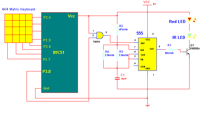
Connections:- Main components of circuit are 89C51 micro controller (datasheet), AND gate 74LS09 (datasheet) and IC NE555 (datasheet). A 4×4 matrix keyboard (total 16 keys) is connected to P1 port as P1.0 to P1.3 pins serves as rows and P1.4 to P1.7 serves as columns. The serial data o/p pin of 89C51 (P3.1 (11)) is connected to one i/p of AND gate chip 74LS09. Second i/p of AND gate is tied to Vcc. The o/p of AND gate drives reset pin (4) of IC-555 which is configured in astable mode. Output of IC-555 drives IR LED through transistor Q1 of 2N2222A (datasheet) type.
Operation:- The heart of circuit is 89C51. It does the main function of generating a specific code for each key when it is pressed. Micro-controller will continuously scans the key board for any key press. When any key is pressed controller will detect it. Then it will assign a specific code to that key and transmit it serially through TXD pin. This code is given to reset pin of IC NE555 through AND gate. AND gate will just work as a buffer.
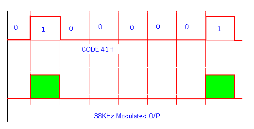
IC 555 is connected in astable mode to generate 38KHz square pulses continuously. Its operation can be ON/OFF by reset pin. Means when reset pin is high o/p is ON and vice versa. So the code generated by micro-controller will be modulated by IR light beam of 38 KHz.
Suppose the code is ‘A’ (41 in HAX). So the binary value 0100 0001 will be transmitted serially and modulated by IC 555. The figure given below will give you better idea.
Programmable receiving unit:-
Let us directly switch on to its different applications. In all these applications the remote control part remains same. Only the receiver part is modified depending upon application.
1) Remote DC Motor speed controller with digital display
2) Remote Stepper motor controller with LCD
3) Multi digit wireless password lock with LCD
Circuit Diagrams
Filed Under: Electronic Projects

Questions related to this article?
👉Ask and discuss on EDAboard.com and Electro-Tech-Online.com forums.
Tell Us What You Think!!
You must be logged in to post a comment.