Shopping carts are handy, but all these carts require a push or pull to move around. How about we create a battery-operated cart that doesn’t require human efforts?
In this project, we will design a mini motorized battery-powered shopping cart using four DC motors attached to four wheels, which can be controlled using a Bluetooth app on your smartphone with joystick-type remote control.
Building a motorized shopping cart
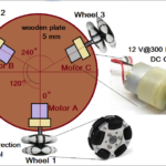
This shopping cart can be built by using readily available items such as a shopping basket, four 10” wheels (used in robotic cart), four DC gear motors (12V @ 300 RPM), PVC pipes, and an acrylic sheet.

Fig. 1: Complete prototype image of a motorized cart.
Required items for cart
- Shopping basket – its a 30” x 20” x 15” plastic shopping basket
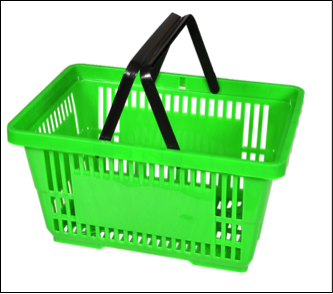
Fig. 2: Image showing shopping basket
- PVC pipes T-joints, L-Joints – we require 4 L-joints, 2 T-Joints, 1” PVC pipe
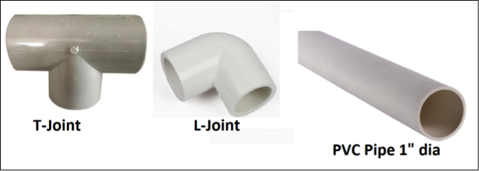
Fig. 3: Image showing various pipes and joints
- Acrylic sheet – it’s a 3’ x 1.5’ 4mm thick transparent acrylic sheet

Fig. 4: Image showing transparent acrylic sheet
- Wheels – Four wheels of 10” diameter
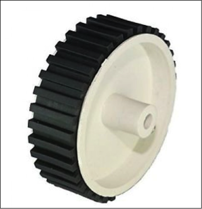
Fig. 5 Image showing wheels
- DC gear motors – four DC gear motors of 12V 300 RPM
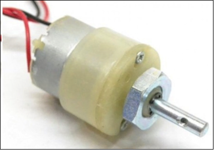
Fig.6: Image showing DC gear motors
When you have all the required items, follow the step-by-step process of building the cart.
Step 1: Build a frame structure using PVC pipes, T-joints, and L-joints. The frame size is about 3’x 1.5’ (36” x 20”).
Step 2: Fix the acrylic sheet of 3’x 1.5’ on the PVC pipe frame using screws and prepare a base for the shopping basket.
Step 3: Fix the shopping basket of 2’x1.5’ on the acrylic sheet base using screws as well as fevicol.
Step 4: Attach a 10” wheel directly to the DC motor shaft using the given screws.
Step 5: House and fix two motorized wheels side by side inside 2” diameter PVC pipe and prepare front, left, and right wheels. Prepare rear left and right wheels in the same manner.
Step 6: Finally, fix all four front and rear wheels with a PVC pipe frame using clamps and screws. Motorized shopping cart is ready.
Here are a few snapshots that will give a complete idea of how to build the cart.
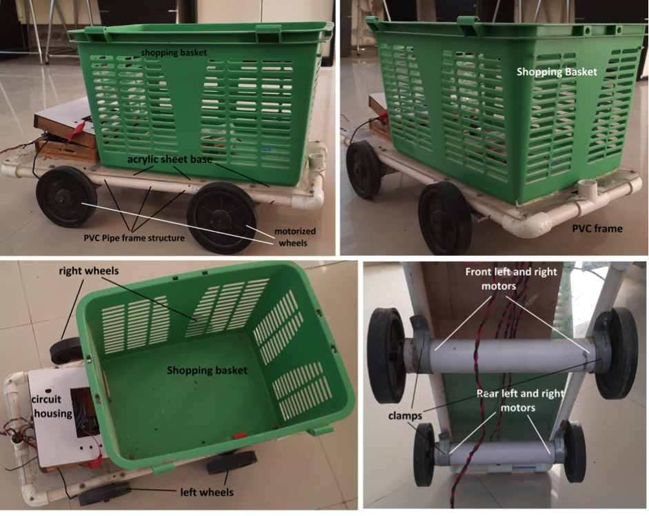
Fig. 7: Image showing steps to create cart using the components
It’s time to build its controlling circuit and remote control. So, let us start with the system block diagram.
System block diagram
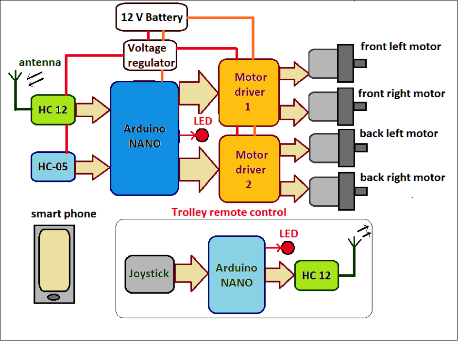
Fig. 8: The primary building block of the working cart system using smartphones and joystick.
The figure shows the primary building blocks of the system. The complete system can be divided into two different sections.
- Shopping cart controlling system
- Joystick remote control
The shopping cart is moving, and the controlling system is built using four DC motors, Arduino NANO board, 2 DC motor driver modules, Bluetooth module HC05, and RF trans-receiver HC12.
The joystick-based remote control is built using 2-axis resistive joystick, Arduino NANO board, and HC-12 transceiver module.
HC-12 transceiver module
It is used as a transmitter in remote control and as a receiver in a shopping cart. It is used to transmit commands from a remote control, and the receiver in the shopping cart receives these transmitted commands. It works on 433 MHz frequency, and it ranges 1100 meters.
HC05 Bluetooth module
This module is used to receive commands from the user’s smartphone through the Bluetooth android app. It receives commands and gives them serially to the Arduino board microcontroller.
Joystick
It is used for sending commands to move forward-reverse-left-right from the remote control to the shopping cart.
Arduino NANO board
The Arduino board in the shopping cart performs all the following tasks
- It gets commands to move the cart from HC12.
- It takes commands to move the cart from HC05.
- It moves the cart in the desired direction like forward-reverse-left-right by rotating all four motors.
Using the remote control, the Arduino board gets commands from the joystick to move forward-reverse-left-right and transmit it using the HC12.
Motor driver module
It is used to drive two DC motors. It provides sufficient voltage and current to both motors.
DC m,otors
4 DC gear motors are attached to four wheels of the shopping cart that give the desired motion to cart.
Battery
A 12 V battery provides a power supply to the entire shopping cart circuit.
Voltage regulator
It is used to supply regulated 5 V to Arduino board and motor driver module.
To start building the circuit, first, you need to collect all required items. Here is the list of items necessary to make both circuits
Required items for remote control and shopping cart circuit
- HC12 transceiver module
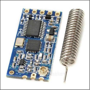
Fig. 9: Image showing HC12 transceiver module
- HC05 Bluetooth module
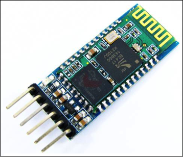
Fig. 10: Image showing HC05 Bluetooth module
- L298 motor driver module
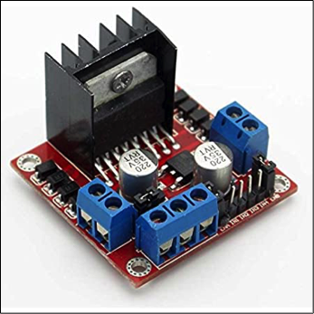
Fig. 11: Image showing L298 motor driver module
- Two-axis joystick
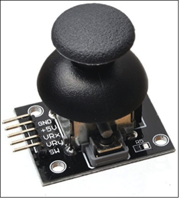
Fig. 12: Image showing two-axis joystick
- Arduino NANO board

Fig. 13: Image showing Arduino NANO board
- 7805 voltage regulator
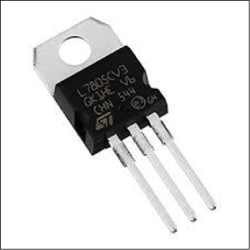
Fig. 14: Image showing 7805 voltage regulator
Now let us see a detailed design of the system with a circuit diagram of its working and operation.
Joystick remote control circuit diagram
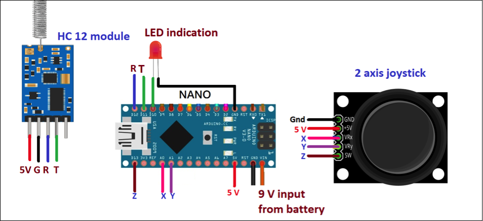
Fig. 15: Image showing a complete circuit diagram of the joystick remote control
The remote control circuit uses only three components 2-axis joystick, an HC12 transceiver module, and an Arduino NANO board.
- The joystick has a 5-wire interface (1) +5V (2) Gnd (3) VRx (4) VRy (5) SW. 5V and GND pins are connected with Arduino board 5V and Gnd pins that give 5V supply to internal joystick POTs
- VRx pin is the slider (middle) terminal of horizontal (X) POT, and it is connected with Arduino analog input A0
- VRy pin is the slider (middle) terminal of vertical (Y) POT, and it is connected with Arduino analog input A1.
- The joystick’s internal push-button terminal SW is connected to digital pin 13 of the Arduino board.
- HC-12 module has a four-wire interface (1) Vcc (2) GND (3) Tx, and (4) Rx. Vcc and Gnd pins are connected with Arduino board 5V and GND pins that give a 5V supply to the module.
- Its Tx and Rx pins are connected with Arduino board digital pins D12 and D11.
- One LED is connected to digital pin D10 to indicate transmission.
Shopping cart circuit
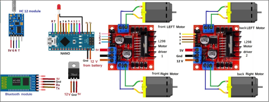
Fig. 16: Image showing circuit of shopping cart
The figure shows that the shopping cart circuit is built using the HC05 module, HC12 module, 7805, two L298 motor driver modules, and Arduino NANO board.
- HC-12 module is connected in the same way as it is connected to the remote control. Its four pins are connected with +5 V, GND, D12, and D11 pins of the Arduino board
- HC-05 module also has four wire interfaces (1) Vcc (2) GND (3) Tx, and (4) Rx. Vcc pin is given +5 v supply from 7805, and GND pin is connected to circuit ground
- Tx and Rx pins are connected with Arduino board Rx and Tx pins (D0 and D1), respectively
- Arduino drives four DC motors using two L293D motor driver modules
- Arduino pins D2-D3-D4-D5 are connected to four inputs of L293D module 1. The four outputs of module 1 drive two front DC motors (left & right)
- Similarly, pins D6-D7-D8-D9 are connected to four inputs of module two. Its four outputs drive rear DC motors (left & right)
- Both motor driver modules get a 12 V motor supply from the battery. Arduino board is also given 12 V supply to Vin pin from the battery
- 7805 IC provides regulated 5 V output (from 12 V battery ) that is given to HC12, HC05, and both motor driver modules
- One LED is connected to digital pin D10 for indication
Circuit working and operation
First, let us see the working of the remote control.
Working with remote control is pretty simple. In just a single line of explanation, it transmits different commands to move cart when the joystick is moved left-right or up-down.
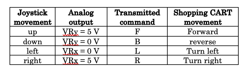
- As the user (operator) moves the joystick in X (horizontal – left or right) or Y direction (vertical – up or down), the internal X and Y POTs change, and this will vary the analog outputs VRx and VRy from 0 to 5 V
- These outputs are given as analog inputs to Arduino. Arduino will read these analog inputs, and based on a change in values of VRx and VRy, it will send and transmits the following commands to the shopping cart using HC12
- The commands are given to the HC12 module serially. The HC12 module transmits these commands using a 433 MHz carrier frequency.
- The led blinks whenever a command is transmitted.
Now let us see how the shopping cart circuit works.
Again in a single line, this circuit moves the shopping cart in all four directions, forward-reverse-left-right, as per the command received from the remote control or smartphone.
- The command transmitted by the HC12 module of remote control is received and demodulated by the HC12 module in the receiver. It gives this command serially to the Arduino microcontroller.
- Similarly, if a smartphone controls the trolley, the Bluetooth controlling android app sends commands to move cart, and the HC05 Bluetooth module receives it. The HC05 module further gives this command serially to Arduino (Note: before sending commands to the HC05 module, the operator (user) has to pair their smartphone with the HC05 module. For pairing the first time, it requires a passkey that is by default “1234”)
- The LED blinks whenever the command is received from a remote or a smartphone.
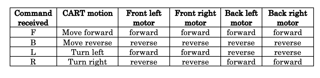
- When Arduino gets the command to move cart, it rotates all four motors per the following table. It gives signals to rotate motors through the L293D motor driver modules. The module will rotate motors either forward or reverse as per the required motion of cart.
The remote control and shopping cart circuits are working and operating based on the program downloaded into Arduino microcontroller (ATMega328) internal FLASH memory. The next thing is to go through the software programs for remote control and shopping cart Arduino microcontrollers.
Software program
There are two programs, one for remote control and the second for the shopping cart. The remote control program reads analog input from the joystick and decides whether it is moved left-right-up-or down. It sends and transmits commands through serial communication using the HC12 transceiver. The shopping cart program reads commands through serial communication from the HC12 transceiver and drives all four motors forward and reverse to move the cart.
Both programs are written in C programming language using Arduino IDE and they are compiled and uploaded into Arduino microcontroller internal FLASH.
Here is the code for both programs
Youtube video links for this project
https://www.youtube.com/watch?v=2Tex1PLughM
https://www.youtube.com/watch?v=YUFgDDJky6I
You may also like:


Filed Under: Electronic Projects

Questions related to this article?
👉Ask and discuss on EDAboard.com and Electro-Tech-Online.com forums.
Tell Us What You Think!!
You must be logged in to post a comment.