Loop calibrators are commonly used in process calibration and control. As its name implies, process control monitors and controls a process to maintain a quality and performance standard. The process can be a physical quantity, such as pressure or temperature. Loop testers can also be used for electrical calibration. In such cases, they verify the performance of an instrument that measures electrical quantities like voltage, current, capacitance, inductance, resistance, time, and frequency.
A Unit Under Test (UUT) is an electrical measurement device (such as a voltmeter or an ammeter) that undergoes electrical calibration. Typical devices include loop testers, oscilloscopes, multimeters, frequency counters, dataloggers, electrical meters, and isolation testers.
In this article, we’ll discuss loop testing, current loops, and the use of loop calibrators, particularly in relation to process calibration.
What is loop testing?
Process calibration is important to ensure industrial safety, efficiency, and productivity. Advanced instrumentation, like digital instruments and multivariable instruments, requires sophisticated calibration tools that can communicate with industrial networks, including HART and Fieldbus. They must ensure high accuracy field calibration.
Typically, such calibration instruments have software to store and analyze detailed and complex instrumentation data. The data is extensively used to produce calibration certificates and reports.
Calibration instruments often rely on advanced techniques based on loop testing.
Conventional instrumentation testing has depended upon individual instrument testing, which is time-consuming and impractical in many situations. Today’s advanced techniques rely more on loop or partial loop testing. The complete process loop is calibrated as a unit instead of as an individual instrument. It tests for the overall tolerance of the loop to ensure efficient control, quality, safety, and minimum downtime.
An example of a process loop is a temperature loop. In this loop, a temperature device (an RTD or a thermocouple) is connected to a transmitter, which is joined to a local indicator and a PLC/DCS input card. In an end-to-end loop test, the temperature element is separated from the process loop, and the performance is evaluated against a simulated temperature.
Unlike the newer, end-to-end loop testing, conventional instrument testing relies on a manufacturer’s specification sheets. The specifications might not quote actual accuracy or include repeatability, long-term stability, temperature effects, or other environmental factors.
However, end-to-end loop testing can be costly or might not be ideal as a sensor or measuring instrument. In such cases, partial loop testing is useful. In the temperature process example, the partial test can be conducted by isolating the temperature device from the transmitter. It can simulate signals to the transmitter with the help of a loop calibrator. Remember, in full loop testing, the entire loop is calibrated instead of an individual instrument.
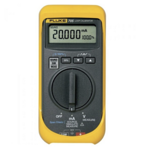
A loop calibrator is one instrument commonly used for loop testing. Loop calibrators are useful in instrumentation testing and for the initial calibration of the process loops. For example, a submersible level transmitter cannot be field-tested in an electronics lab. But a loop calibrator can be used to simulate the signals of the level transmitter to calibrate the control circuitry. Later, the control circuit can be field-tested with an actual level transmitter at the testing site.
The 4-20 mA current loops
Loop calibrators are often designed to work with 4-20 mA current loops. They can measure currents, supply current to unpowered devices in the current loop, and simulate signals as the loop-powered transmitters.
The 4-20 mA current output is the typical electrical signal generated by sensors and instruments. The sensor or instrument within a series acts as a constant current source, where the current output depends upon the measured physical quantity like temperature or pressure.
The current signal provides an output signal because it remains the same at all points in the series network. It also allows for high-powered analog output, which can be transferred over long distances.
The current signal can be converted to a measurable voltage at any point in the network by connecting a series resistor. For instance, the 4-20 mA current can be converted to a voltage range between 1~5V by connecting a 250Ω resistor to the series. If doing so, ensure the 4-20 mA transmitter has sufficient voltage between its positive and negative lines, so the measurement is not comprised at full scale. The 4-20 mA current signal works easily with a two-wire connection and holds strong against radio-frequency interference or other potential error sources.
Why 4-20 mA?
Current loops are typically set to 4-20 mA standard. The standard starts with 4 mA (and not 0 mA) has historical and technical reasons.
Before electronics became the industry it is today, process instruments were mechanically calibrated. For mechanical calibration, 3~15 psi was the standard. Anything below 3psi was unrecognizable. Additionally, 0 psi was easy to identify as a system failure. When electronic controllers replaced mechanical calibrators, the 4-20 mA range was selected to reflect the same 3~15 psi range.
Similarly, with electronic controllers, 0mA is too low to detect and is better suited to indicate a system failure.
What is a loop calibrator?
A loop calibrator is an electrical calibrator that:
- Troubleshoots 4-20 mA current loops
- Simulates signals as loop-powered transmitters
- Calibrates current loops
- Measures electrical current
- Sources current to unpowered devices in current loops
- Performs loop testing
Loop calibrators operate over a wide power supply, transmitting signals over long distances without loss or noise. These instruments can also measure electrical current, source current, and simulate as loop-powered 4-20 mA transmitters.
Two or four wires?
Loop calibrators can be used with two and four-wire transmitter configurations. In a two-wire transmitter configuration, the measurement signal uses only two connections for the power supply and output signal.
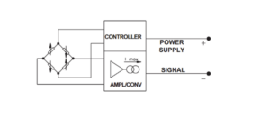
A two-wire 4-20 mA loop transmitter.
In a four-wire transmitter configuration, the power supply and output signal are isolated using a Wheatstone bridge network. This configuration is more accurate because it independently compensates for errors.
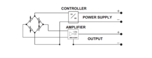
A four-wire 4-20 mA loop transmitter.
The 250Ω resistor connection
To convert a 4-20 mA current signal to between 1~5V, connect a 250Ω resistor. To clarify a common misconception about whether a series or parallel connection is used with the resistor, this may help:
- If the DCS/PLC input card accepts the 1-5Vdc input, the 250Ω resistor must be connected in parallel to the input 1-5Vdc wires.
- If the measurement must be done from the current-loop network to work, the 250Ω resistor must be connected in a series with the 4-20 mA current loop.
Measuring the current
To measure the current with a loop calibrator:
- Disconnect the current loop from the negative terminal
- Connect the loop calibrator as a load between the loop-powered transmitter and the local indicator controller
- Note: the loop-powered transmitter can be a temperature, pressure, level, float-level sensor — or another process instrument
- The loop calibrator’s toggle switch must be set to the “read” position to measure the electrical current
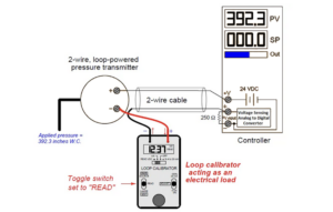
The electrical connections for measuring current with a loop calibrator.
Sourcing current
It’s easy to test a controller or indicator circuit with a loop calibrator, which can source signals in the 4 to 20 mA range. It’s useful for calibration before either device is field-tested with a sensor or process instrument.
To source current:
- The calibrator’s red lead must be connected to the process variable input’s positive terminal
- The calibrator’s black lead must be connected to the process variable lead’s negative terminal
- The loop calibrator’s toggle switch must be set to the “source” position
- The output current signal can be set using the adjustable knob
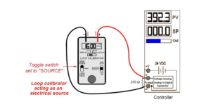
The electrical connections for sourcing current with a loop calibrator.
Simulating a loop-powered transmitter
The loop calibrator can also be used to simulate a loop-powered transmitter. Here’s how it works:
- The calibrator’s red lead connects with the process variable input’s supply terminal
- The calibrator’s black lead connects with the process variable input’s positive terminal
- The loop calibrator’s toggle switch must be set to the “two-wire” position
- A predetermined current level is set using the adjustable knob
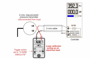
The electrical connections for simulating a loop calibrator as a loop-powered transmitter.
You may also like:
Filed Under: Tech Articles

Questions related to this article?
👉Ask and discuss on Electro-Tech-Online.com and EDAboard.com forums.
Tell Us What You Think!!
You must be logged in to post a comment.