This era is an era of portable devices. Like smartphones and tablets are small computers that can be taken anywhere, more and more gadgets that can be taken anywhere are the new craze. These light-weight and portable devices are being developed in domains of electronic applications. All such devices are run on batteries. The batteries are the lifeline of all such devices. The use of batteries itself though requires certain precautions. The most common issue with the use of batteries is their overcharging and over discharging. Also, it is important to keep track of the charge level of batteries attached to a device, so that it can be timely charged before it discharges to the level that the device gets nonoperational. For the same purpose, the devices that run on batteries must have a battery charge indicator.
Secondly, some batteries have high tolerance limit for overcharging and some may explode after a certain limit of charging. That is why it is important to disconnect the battery from charging when it reaches its maximum limit. A battery level indicator gives the visual indication of the battery state and so allow disconnecting it before over charging. Also, by battery level indicator, the user is instigated to charge the battery before it dies.
Depending upon the state of battery there are two ways to indicate charge level, one is the state of charge (SOC) method and another is the death of discharge (DOD) method. SOC is the measure of the stored charge in the battery and DOD is the measure of the degree by which battery is getting emptied relative to the total capacity of the battery.
In this project, a battery level indicator is designed using state of charge method. SOC method is more convenient to use and easy to design. SOC of the battery can be determined by the voltage level at the terminals of the battery or by measuring current output of the battery. In this project, the SOC of a battery is determined by sensing the terminal voltage level of the battery. Therefore, for sensing the voltage level of the battery, an integrated circuit is required which can precisely detect the voltage across the terminals of the battery.
In this project, a 12V Lead Acid battery is used. with a voltage rating of 12 V, this battery has maximum charging voltage at 13.5 V and end of discharge voltage at 10.5 V. The end of discharge voltage is the voltage below which any device connected to the battery will stop operating. For sensing the terminal voltage level of the battery series, LM339 IC is used.
LM339 is a single supply quad comparator which has four channels to detect the magnitude of analog voltages and indicate the voltage level by lighting up to 4 LEDs. So, the IC is designed to indicate four voltage levels respective to a common voltage reference. For voltage indication, LEDs can be connected to the IC. Each LED draws current in the range from 5 mA to 6 mA current. Practically, it is seen that LEDs indicated the voltage level from 10.45V to 13.5V.
Components Required

Fig. 1: List of Components required for LM339 IC based Battery Level Indicator
Circuit Connections –
For designing this battery level indicator it is important to understand pin diagram and pin configuration of LM339 IC. This is a comparator IC which is specially designed for low-level sensing. Internally LM339 consists of four OPAM which acts like comparators and detect the voltage level. This IC has low offset voltage (+/- 2 mV) and low bias current (Typically 25 nA). The supply voltage of LM339 can vary from 3V to 36V and split supply can vary from +/-1.5 V to +/-18 V. The input common mode voltage is around -0.3 V to Vcc. The input common mode voltage is the acceptable input voltage range for the operation of LM339.
Ideally, the zero-volt output of OPAM should be zero. But due to a mismatch in the input transistor of OPAM, the OPAM gives zero output at non-zero input values. So, an input offset voltage is needed. This voltage is the required voltage at both the input terminals of the OPAM to make the output voltage zero.
Bias current or input bias current is the leakage current which flows in and out of the input terminal of the OPAM. The range of input bias current is from Nanoamperes to picoamperes. So, MOSFET OPAM has input bias current in picoampere and BJT OPAM has input bias current in nanoampere.
By using LM339 less number of components are required to design the circuit. The IC has low bias current and offset voltage which prevents input common mode supply voltage from going below – 0.3V.
The IC has the following pin diagram and internal circuitry as shown in the figure below –
")
Fig. 2: Internal Circuit of LM-339 (Source- LM339 on semiconductor datasheet)
LM339 is a 14-pin IC with pins having the following functions –

Fig. 3: Table listing pin configuration of LM339 IC
First of all, battery has to be connected with the IC. At input, a battery of 12V is connected and the LM339 IC can sense the battery voltage level and indicate it by output LEDs. The use of C1 capacitor is to remove the unwanted voltage spikes and noise from the input signal which may cause damage to the IC (as shown in the circuit diagram).
For voltage regulation, Zener diode is used. A zener diode D1 (6.2V) will provide a constant and regulated voltage of 6.2V to the non-inverting pin of comparators. The resistance R1 will limit the flow of current to the zener, as current more than zener rating can damage it. The maximum current rating of zener can be calculated as-
Iz = Pz(Power of zener diode)/Vz(voltage of zener diode)
Externally the non-inverting pin of each comparator is set at a fixed voltage level but at different values. This is done by using a zener diode and a string of resistance which makes a voltage divider network. The inverting pin of all the comparators are set at the same potential and keep changing as per input voltage. A diode D2 is connected to the negative supply pin (pin 12) of IC to the ground. As this IC cannot work below -0.3V voltage so this diode provides a drop of around 0.7V and lifts up the ground voltage to 0.7V. Therefore, it prevents the IC from going below -0.3 V. This diode also blocks the small noise signal which may come from the ground and protects the comparator IC.
For visual indication of the terminal voltage level of battery, LEDs at the output pins of the compartors are used. There are four output corresponding to four comparators. At each output, LED is used with a series resistance.This resistance limits the flow of current through LED, as the high current can damage LED. These LEDs will give a visual indication of the voltage level of the battery. In this experiment, the maximum current drawn by each LED is around 5mA to 6mA. The current can be vary by varying the value of resistor from R9 to R12
How the circuit works –
The functioning of this circuit is based on the comparator. A comparator compares two input signals and gives the output indicating which one is larger. If inverting pin of OPAM is higher than non-inverting than output is low otherwise it is high. This concept of comparator can be used in sensing the desired voltage level. When a 12V battery is connected to the zener diode then zener will provide a constant voltage of 6.2V. The drop across resistor R2 to resistor R6 is also constant. This resistance will provide the fixed voltage to the non-inverting pin of the comparator. The drop across each resistance can be calculated as follow –
The Zener voltage, Vz = 6.2V
As the resistor act as a voltage divider network (as shown in the figure below) so the voltage at the non-inverting pin can be calculated by circuit analysis.

Fig. 4: Circuit Diagram of Voltage Divider Network at Comparator Pins
Voltage at non-inverting pin can be calculated as follow –
Voltage at pin 7, V7 =( Vz.Req)/(R2+ Req)
V7 = (6.2*13000)/(5000+13000)
V7 = 4.47V
Similarly, the voltage at pin 5,9 and 11 can be calculated as follow –
V5 = ( Vz.Req)/(R2+R3+ Req)
V5 = (6.2*12000)/(6000+12000)
V5 = 4.12V
V11 = ( Vz.Req)/(R2+R3+R4+ Req)
V11 = (6.2*11000)/(7000+11000)
V11 = 3.78V
V9= ( Vz.Req)/(R2+R3+R4+R5+ Req)
V9 = (6.2*10000)/(8000+10000)
V9 = 3.4V
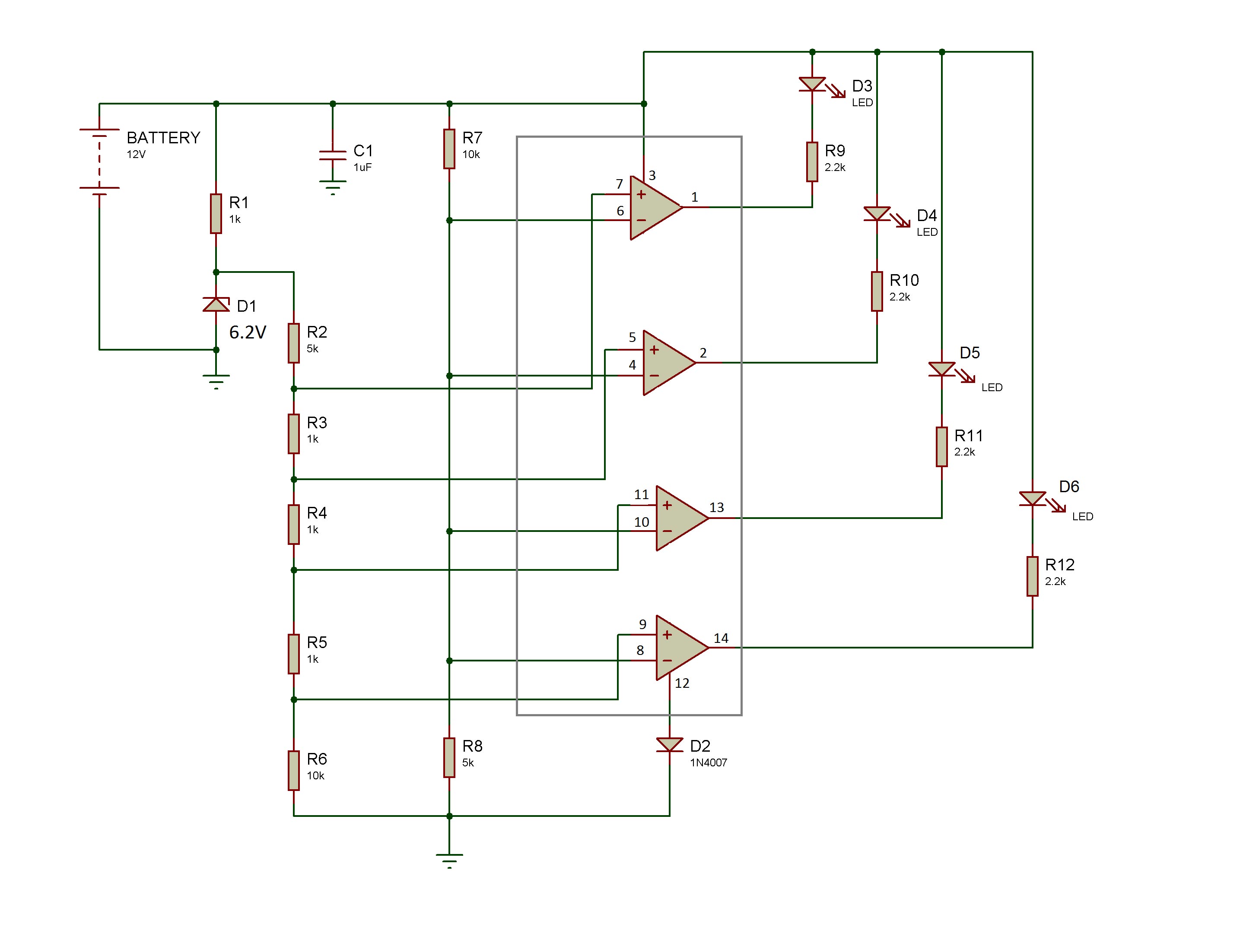
The voltage at inverting pin (4th, 6th, 8th and 10th pin) of all the comparators are same and will vary as per the change in battery voltage (as shown in the figure below). The resistors R7 and R8 makes a resistor divider network which always provides 1/3rd of the battery voltage to the inverting pin of the comparator. When inverting input of the comparator is at high voltage than the non-inverting pin then the output voltage of comparator is low otherwise it is high. This makes cathode of the output LED at low voltage and the anode of LED is already at positive of the battery. This will turn on the LED which will indicate the voltage level of the battery. In other cases, the LED will be in off state.

Fig. 5: Circuit Diagram showing LM339 pin connections for Battery Indicator
Testing the Circuit
There are four voltage levels for which LEDs should indicate the battery voltage which are 10.5 V, 11.5 V, 12.5 v and 13.5 V. The circuit can be tested by measuring the terminal voltage of the battery using a multimeter and comparing the desired LED operation with the actual operation of the LEDs.
When battery voltage is at 10.5 V, voltage at non-inverting pin does not change as per the battery voltage so voltage at non-inverting pin has been calculated as follow –

Fig. 6: Table listing voltage at non-inverting pin of comparator at battery voltage of 10.5V
The Voltage at all inverting pins (4th, 6th, 8th, 10th) of four comparators are same and can be calculated as follows –
Voltage at inverting pin, Vinvert = 1/3*battery voltage
Voltage at inverting pin, Vinvert = 1/3*10.5
Voltage at inverting pin, Vinvert = 3.5V
On comparing voltage at non-inverting pin and inverting pin of four comparators –

Fig. 7: Table listing voltage comparison of voltage at non-inverting pin and inverting pin of four comparators
By comparing the voltages of non-inverting and inverting pin It can be determined that only voltage of non-inverting 9th pin is less than the voltage at inverting input pin 8. So the comparator 1 will give low value and D6 LED will light up.
In a similar way, the values for other battery voltage at 11.5 V, 12.5 V and 13.5V can be calculated. It can be observed that at 11.5 V the second comparator will give low value and D5 LED will light up, at 12.5 V D4 LED will light up and at 13.5 V D3 LED will light up. Therefore at 13.5V all LEDs will glow and this will indicate that the battery is fully charged.

Fig. 8: Prototype of LM-339 Battery Indicator designed on a breadboard
Practically for different terminal voltages of the battery following observations were taken –
1. When the battery voltage was at 10.45V then D6 LED lights up and the battery was at its end of discharge voltage.

Fig. 9: Table listing voltage at inverting and non-inverting pin of comparator at battery voltage of 10.45V
2. When the battery voltage was at 11.4 V then D6 and D5 LEDs light up. This indicated that the battery is around 33.3% charged.

Fig. 10: Table listing voltage at inverting and non-inverting pin of comparator at battery voltage of 11.45V
3. When the battery voltage was at 12.46 V then D4, D5, and D6 LEDs light up. This indicated that the battery is around 66.7% charged.

Fig. 11: Table listing voltage at inverting and non-inverting pin of comparator at battery voltage of 12.46V
4. When the battery voltage was at 13.5 V then D3, D4, D5, D6 LEDs light up. This indicated that the battery is around 100% charged.

Fig. 12: Table listing voltage at inverting and non-inverting pin of comparator at battery voltage of 13.5V
It should be noted that as the LM339 minimum input common mode voltage is -0.3V so a diode is used at the negative supply pin (12th pin) of LM339 IC to ground so it can prevent the voltage going less than -0.3V. It is recommended to use a capacitor at the positive terminal of the battery to the ground so that it eliminates the unwanted ripples and noise from the input signal.
Circuit Diagrams
Filed Under: Electronic Projects

Questions related to this article?
👉Ask and discuss on Electro-Tech-Online.com and EDAboard.com forums.
Tell Us What You Think!!
You must be logged in to post a comment.