In the previous projects, a capacitor for smoothing AC to DC converted signal was used. The purpose of using the filtering capacitor was to protect the load circuit from any fluctuations and ripples in the input voltage. The fluctuations or ripples are quite common when the circuits are powered ON and switched ON or OFF suddenly. In this project, a more robust circuit to handle input fluctuations is designed. The circuit is built using OPAM and SCR. It is used to operate a relay which controls the supply to the load. A rectified 12V supply is assumed at the input of the circuit and same voltage without ripples will be obtained at the output.

Fig. 1: Prototype of OPAMP and SCR based Voltage Guard
The circuit disconnects the load from the supply on receiving excessive fluctuation. The supply could be resumed by pressing a push-to-on switch on the circuit. The supply is assumed to be already converted to 12V DC by passing main supply voltage to a 12-0-12V transformer and a full-bridge rectifier.
Components Required –

Fig. 2: List of Components required for OPAMP and SCR based Voltage Guard
Circuit Connections –
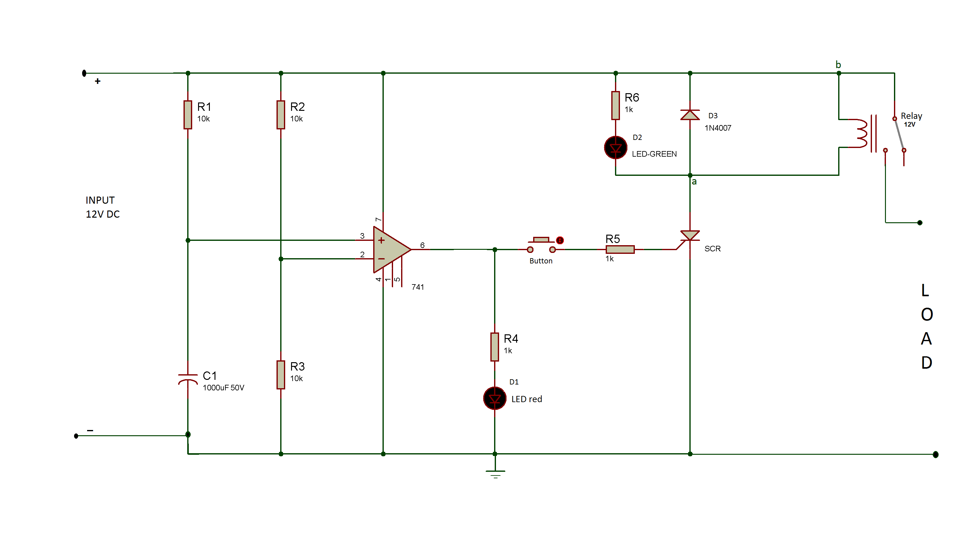
The circuit is built around 741 OPAM IC. The input 12V DC is applied to the non-inverting input of the OPAM through an RC network. The same voltage is applied to the inverting input of the OPAM through a resistive voltage divider (voltage divider is constructed using R2 and R3 resistors in schematics). The negative voltage at pin 4 of the IC is set to ground and a positive voltage at pin 7 is set to input 12V. The output is drawn from the pin 6 of the IC and is passed to the gate pin of SCR via a push-to-on switch. A red LED with a pull-up resistor in series is connected to the output of OPAM to get a visual hint of the supply’s continuity. The cathode of the SCR is connected to the ground while its anode is connected to the anode of diode D3. The coil terminals of a 24V relay are connected across the diode D3 and input 12V is provided at the COM point of the relay. The load is connected between the NO point of the relay and the common ground.
How the circuit works –
The OPAM is connected as a voltage comparator in the circuit. The potential divider circuit formed by resistors R2 and R3 connects at the inverting input of the OPAM. The value of R2 and R3 are same so that they provide half of the input voltage to the inverting pin. Therefore inverting input of OPAM gets 6V at the pin because input voltage is 12V.
When the 12V DC input voltage is supplied to the circuit, initially output from pin 6 of the OPAM is LOW since the capacitor C1 at the non-inverting input of OPAM takes some time to charge up. When C1 is fully charged, the voltage at the non-inverting input of OPAM i.e. pin 3 of IC becomes 12V which is greater than the voltage at inverting input pin 2 which is at 6V. Since the OPAM acts like a voltage comparator, it gives positive voltage i.e. 12V at the output corresponding to the positive voltage at pin 7(12V) of the OPAM. The capacitor C1 is used to maintain the 12V at the pin 3 (Non-Inverting Input) of OPAM. Thus at output 12V is provided by the OPAM. This 12V is then supplied to the LED (D1) which lights up, on reception of the HIGH output. The red LED is used indicate that power is switched on.
When the push-to-on button is pressed, the gate of SCR starts getting a positive voltage which triggers the SCR. The SCR requires little voltage at its gate terminal to get it triggered. It acts as a short circuit and current starts flowing from its anode to cathode through resistance R6 and the green LED turns on. Therefore at point ‘a’ (shown in schematics), the voltage drop is zero as all the current passes to ground through SCR. So, the point ‘b’ is at 12V and the relay gets the required 12V at one end of its coil energizing it. The normally open (NO) point of the relay gets connected to the Common pin (C) and supply is provided to the load. The green led in the circuit indicates that the load is provided the supply.
When there is a power failure and the power resumes afterward, there is a chance of getting high spikes in the input supply voltage. These spikes can damage the load circuit. In the circuit anode of SCR does not get any voltage across it so it remains turned OFF. So the relay also does not get supply voltage and remains de-energized. Therefore the load remains disconnected with the power supply. Until push-to-on button is pressed the gate pin of SCR is not triggered and relay remains de-energised keeping the load out of power supply. The diode D3 connected parallel with the relay is used to prevent the circuit from the back current by the inductor of the relay when power fails. Thus the inductor gets discharged through this diode in case of power failure.
When power resumes the push-to-on switch has to be pressed to trigger the SCR again which in turn operates the relay and resumes power to the load. The circuit helps in reducing the risk of voltage spike at the input of load whenever power resumes after failure and so prevents the load from damage.
Testing and Precautions –
The following precautions should be taken while assembling this circuit –
The current and voltage rating of the relay must be greater than or equal to the current which is to be driven at the output. Otherwise, it will be unable to supply the required current and voltage at the output.
The SCR must be chosen as per the required current and voltage rating.
The D3 diode should be connected to the input of relay in parallel to reduce the risk of back current from the coils of the relay during the power failure.
A voltage divider circuit should be used which maintains the lower voltage at the inverting pin of OPAM compared to non-inerting pin.
A capacitor C1 should be used to maintain a constant voltage at non-inverting of the OPAM.
Once the circuit is assembled, it should be tested with a 12V DC supply. The input supply should be switched ON and OFF and status of red and green LEDs should be monitored to verify the functioning of the circuit.
This circuit can be used as a voltage guard for protection against fluctuations on power failure.
You may also like:


Circuit Diagrams
Filed Under: Tutorials

Questions related to this article?
👉Ask and discuss on Electro-Tech-Online.com and EDAboard.com forums.
Tell Us What You Think!!
You must be logged in to post a comment.