SPI and I2C are the common serial communication protocols used by sensors for communicating with microcontrollers and microcomputers. Both protocols are master-slave protocols. The sensors often take the part of a slave device within an embedded ecosystem. Most of the time, a sensor only requires sending data to the microcontroller/microcomputer. This remains true even if a given sensor is interrupt-enabled.
Several embedded devices include many sensors that require full-duplex communication with the controller. These are usually sophisticated sensors and embedded modules with their own explicit command set and a broader scope of configuration or those capable of transmitting a wide range of varied data. Such sensors and embedded modules rely on the full-duplex SPI protocol — which allows the controller to exchange data with multiple devices on a common bus — for data communication with the controller. SPI is also a synchronous communication protocol that allows a high-speed chip-to-chip link. The data speed on the SPI bus can max up to 10 Mbps.
SPI Vs. I2C
SPI stands for Serial Peripheral Interface. It is a full-duplex serial communication protocol in contrast to I2C, a half-duplex serial protocol. By full-duplex means that the SPI bus simultaneously allows both transmission and reception of data between the controller and the slave. There are separate data lines on the SPI bus for data transfer from the controller to the controller. Contrary to this, I2C has a single data line, so at a time, either controller can send data or receive data but not both. While the I2C bus has only two lines – a data line and a clock line, an SPI bus has three or four lines. There are two data lines, MISO (for data transfer to the controller from the slave) and MOSI (for data transfer to the slave from the controller), one clock line SCK, and a chip select or slave select line CS/SS. In the I2C protocol, multiple slaves can be connected to two lines where the slaves are recognized and selected for data communication using an addressing mechanism. In SPI, if multiple slaves are connected, the Chip Select line is required. Each slave has its own chip select line. This increases the number of data pins engaged on the controller as more slave devices are added to the SPI bus. While the I2C protocol ensures the successful transmission of data using acknowledgments, the SPI protocol has no such mechanism. The data transmission is not guaranteed in the SPI protocol.
While the requirement of additional chip select lines and lack of data verification are the main cons of SPI protocol. It has a lot to offer in the embedded scenario. It allows full-duplex data communication at high speeds up to 10 Mbps. The data transmission speed on the I2C bus can max at 3.4 Mbps. The SPI bus requires less power for data communication and is highly efficient for short distances. If an embedded block has to be integrated on-board with the controller, the SPI is a cut above I2C.
MicroPython machine module
The MicroPython’s machine module is written for handling hardware functions of the supported ports. The module includes classes for controlling digital input/output, controlling output signals from external devices, pulse width modulation, analog to digital conversion, controlling ADC peripherals, UART, SPI, I2C, I2S, Timer, RTC, Watchdog timer, and managing SD card. It has the SPI class for managing hardware I2C and SoftSPI for implementing software SPI in the supported ports.
SPI class
The SPI class of machine module is responsible for implementing SPI protocol in MicroPython-supported ports. The SPI bus has three lines – MOSI, MISO, and SCK. The synchronous protocol requires an additional CS line per slave, provided multiple slaves are connected to the SPI bus. The CS signal is managed with the help of the PIN class of the machine module. Both hardware and software SPI are available in MicroPython. The hardware SPI utilizes the underlying SPI peripheral of the supported ports. The SPI pins in most of the ports are fixed. Though it is not that efficient, the software SPI can be applied to all output-capable pins of a port. The SPI class is included in a MicroPython script using the following statement.
from machine import SPI, Pin
After importing the SPI and PIN class, an object of the SPI class must be instantiated using the constructor method. The constructor method of the SPI class has the following prototype.
class machine.SPI(id, …)
A call to the constructor method essentially requires one argument, the id. The id is the identification of the hardware SPI block. It can be a number or string depending upon the specific port. Usually, the SPI blocks are identified by numbers like 0, 1, 2, etc. The other arguments that can be passed in a call to the constructor method are configuration parameters. The configuration parameters set in the constructor method include baud rate, polarity, phase, bits, firstbit, sck, mosi, miso, and pins. The baud rate is the SCK clock rate. The maximum baud rate that can be set depends on the specific port. The polarity sets the level of the idle clock line. It can be set to 0 or 1. The phase determines whether data is sampled at the first or second clock edge. If the phase is set to 0, data is sampled at the first clock edge; if it is set to 1, the data is sampled at the second clock edge. Firstbit determines if the first bit in data is LSB or MSB. It can be set to SPI.LSB or SPI.MSB. Some ports allow alternative pins for MOSI, MISO, and SCK. The mosi, miso, and sck arguments set the MOSI, MISO, and SCK pins, respectively, in such ports. If not specified, default MOSI, MISO, and SCK pins are set. The pins argument is only allowed for the WiPy port. It allows specifying a tuple for setting the MOSI, MISO, and SCK pins. Some of the valid examples of creating SPI objects are the following.
spi = SPI(0)
spi = SPI(0, baudrate=400000)
hspi = SPI(1, 10000000)
hspi = SPI(1, 10000000, sck=Pin(14), mosi=Pin(13), miso=Pin(12))
vspi = SPI(2, baudrate=80000000, polarity=0, phase=0, bits=8, firstbit=0, sck=Pin(18), mosi=Pin(23), miso=Pin(19))
After creating an SPI object, it can be initialized using the SPI.init() method. It takes in the same arguments as the constructor method except the id. The SPI.init() method has the following prototype.
SPI.init(baudrate=1000000, *, polarity=0, phase=0, bits=8, firstbit=SPI.MSB, sck=None, mosi=None, miso=None, pins=(SCK, MOSI, MISO))
The other methods available in the SPI class are as follows:
SPI.deinit(): This method turns off the SPI bus.
SPI.read(nbytes, write=0x00): This method reads the number of bytes nbytes while writing a single byte specified by the write argument to the MOSI line. It returns a byte object containing the read bytes from the MISO line.
SPI.readinto(buf, write=0x00): This method reads bytes from the MISO line into a buffer object while writing a single byte specified by the write argument to the MOSI line. The read bytes are stored in the buffer object. The number of bytes read depends upon the size of the buffer object. The method returns nothing.
SPI.write(buf): This method writes the bytes stored in a buffer object buf to the MOSI line. It returns nothing.
SPI.write_readinto(write_buf, read_buf): This method writes bytes from a buffer object write_buf to the MOSI line and reads bytes into a buffer object read_buf. Both buffer objects can be the same but should be the same length. The method returns nothing. The number of bytes in write_buf are written over the bus, and the number of bytes equal to the length of read_buf are read and stored in the read_buf object.
SoftSPI class
The software SPI is implemented by bit-banging. The SoftSPI class is imported in a MicroPython script using the following statement.
from machine import Pin, SoftSPI
The SoftSPI has all the same methods as the hardware SPI class. The constructor method of the SoftSPI has the following prototype.
class machine.SoftSPI(baudrate=500000, *, polarity=0, phase=0, bits=8, firstbit=MSB, sck=None, mosi=None, miso=None)
Following is valid example of instantiating software SPI object.
spi = SoftSPI(baudrate=100000, polarity=1, phase=0, sck=Pin(0), mosi=Pin(2), miso=Pin(4))
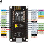
Hardware SPI in ESP8266
There are two SPI blocks in ESP8266 – SPI0 and SPI1. The SPI0 remains reserved for Flash ROM and cannot be used in the user program. The SPI1 has MISO, MOSI and SCK pins fixed at GPIO12, GPIO13, and GPIO14 respectively.
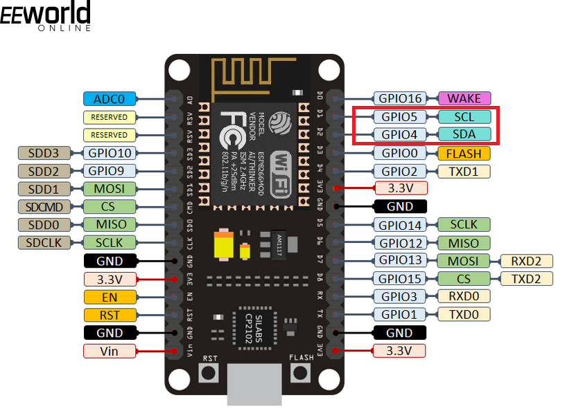
Default SPI pins on ESP8266
The maximum clock frequency can be set to 80 MHz. The following is a valid example of creating a hardware SPI object in ESP8266.
from machine import Pin, SPI
hspi = SPI(1, baudrate=80000000, polarity=0, phase=0)
Software SPI in ESP8266
Software SPI is one of the two SPI drivers available in ESP8266. The software SPI can be implemented on all pins of the ESP8266. Following is valid example of using MicroPython software SPI in ESP8266.
from machine import Pin, SoftSPI
spi = SoftSPI(baudrate=100000, polarity=1, phase=0, sck=Pin(0), mosi=Pin(2), miso=Pin(4))
spi.init(baudrate=800000)
spi.read(3) # read 3 bytes on MISO
spi.read(3, 0xff) # read 3 bytes while outputting 0xff on MOSI
buf = bytearray(10) # buffer object
spi.readinto(buf) # read 10 bytes into the given buffer
spi.readinto(buf, 0xff) # read 10 bytes into the given buffer and output 0xff on MOSI
spi.write(b’12345′) # write specified buffer object on MOSI
buf = bytearray(5) # create a buffer
spi.write_readinto(b’12345′, buf) # write to MOSI and read from MISO into the buffer
spi.write_readinto(buf, buf) # write buf to MOSI and read MISO back into buf
Hardware SPI in ESP32
There are two hardware SPI blocks in ESP32 – HSPI (SPI1) and VSPI (SPI2). The default pins for MOSI, MISO, and SCK of HSPI are GPIO13, GPIO12, and GPIO14, respectively. The default pins for MOSI, MISO, and SCK of VSPI are GPIO23, GPIO19, and GPIO18, respectively. The maximum SPI clock frequency can be 80 MHz at the default pins. ESP32 allows GPIO multiplexing of the hardware SPI blocks, provided the pins are input-enabled or output-enabled as per the requirement of the SPI line. However, the maximum SPI clock frequency at multiplexed pins can be only 40 MHz.
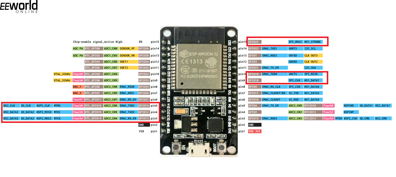
Default SPI pins on ESP32
The following is valid example of creating a hardware SPI object in ESP32.
from machine import Pin, SPI
hspi = SPI(1, 80000000)
hspi = SPI(1, 40000000, sck=Pin(14), mosi=Pin(13), miso=Pin(12))
vspi = SPI(2, baudrate=80000000, polarity=0, phase=0, bits=8, firstbit=0, sck=Pin(18), mosi=Pin(23), miso=Pin(19))
Software SPI in ESP32
The software SPI is available on all pins of ESP32. The maximum clock frequency of software SPI can be 40 MHz. Following is a valid example of software SPI in ESP32.
from machine import Pin, SoftSPI
spi = SoftSPI(baudrate=100000, polarity=1, phase=0, sck=Pin(0), mosi=Pin(2), miso=Pin(4))
spi.init(baudrate=800000)
spi.read(3) # read 3 bytes on MISO
spi.read(3, 0xff) # read 3 bytes while outputting 0xff on MOSI
buf = bytearray(10) # buffer object
spi.readinto(buf) # read 10 bytes into the given buffer
spi.readinto(buf, 0xff) # read 10 bytes into the given buffer and output 0xff on MOSI
spi.write(b’12345′) # write specified buffer object on MOSI
buf = bytearray(5) # create a buffer
spi.write_readinto(b’12345′, buf) # write to MOSI and read from MISO into the buffer
spi.write_readinto(buf, buf) # write buf to MOSI and read MISO back into buf
Some SPI examples
Some of the good examples of using the MicroPython SPI class can be found in the following projects.
- Project – MicroPython SSD1351 by author rdagger
- Project – MicroPython nanoGUI by author peterhinch
- Project – uPySensors by author lemariva
- Project – uble by author dmazzella
Check out the above-embedded projects and explore their source code to know how SPI class of the MicroPython machine module is used.
You may also like:
Filed Under: Electronic Projects, ESP8266., Microcontrollers, Python, Sensors, Sensors, Tech Articles, Tutorials

Questions related to this article?
👉Ask and discuss on Electro-Tech-Online.com and EDAboard.com forums.
Tell Us What You Think!!
You must be logged in to post a comment.