Microcontroller boards require communicating data with a lot of other devices that include sensors, actuators, other microcontrollers, and microcomputers. This data transfer or exchange is carried over serial interfaces using standard protocols like UART, I2C, SPI, 1-wire, etc. UART is one of the common serial data communication protocols available on almost every microcontroller. UART is a peer-to-peer bidirectional serial data communication protocol. The sensors usually communicate data with microcontrollers and microcomputers using I2C or SPI protocols as sensors always behave as slave devices that generally only require transmitting data to the microcontrollers/microcomputers. There is hardly any need for bidirectional data communication by sensors.
However, any data communication with other microcontrollers or microcomputers strictly needs to be peer-to-peer and bidirectional. UART is the most useful serial communication protocol in this scenario. The UART protocol is useful when a microcomputer or other master microcontroller guides networked microcontroller systems like ESP8266 or ESP32. This article will look at the UART class of the MicroPython machine module and explore how that can be used for serial data communication in ESP8266 and ESP32.
MicroPython machine module
Apart from re-implemented Python3 modules, MicroPython has several native modules to deal with hardware functions and devices. One of these modules is a machine responsible for handling many vital microcontroller functions. The module includes classes for controlling digital input/output, controlling output signals from external devices, pulse width modulation, analog to digital conversion, controlling ADC peripherals, UART, SPI, I2C, I2S, Timer, RTC, Watchdog timer, and managing SD card.
UART class
UART class is a part of the machine module. It implements standard UART/USART protocol. UART requires two lines – Rx and Tx for full-duplex communication. The Rx and Tx of one microcontroller is connected to the Tx and Rx of the other, respectively. This class is imported in a MicroPython script using the following statements.
from machine import UART
The instantiation of a UART object must follow this. The constructor function for the UART object is as follows.
class machine.UART(id, …)
The constructor method essentially requires specifying the UART ID as an argument. Many other arguments can be passed within the constructor method. These arguments are the same as defined for the UART.init() method. We will discuss them shortly. Some of the valid examples of instantiating a UART object are the following.
uart = UART(0)
uart = UART(0, baudrate=9600)
uart1 = UART(1, baudrate=9600, tx=33, rx=32)
The other methods available in the UART class are the following.
UART.init(): This method is used to initialize the UART object. It has the following prototype.
UART.init(baudrate=9600, bits=8, parity=None, stop=1, *, …)
The following parameters are passed to the method call.
baudrate: This is the baud rate in bps. It must be passed as an argument.
bits: It is the number of bits per character. It can be 7, 8 or 9. The default is 8.
parity: It specifies the parity bit. It can be even (0) or odd (1).
stop : It specifies the number of stop bits. It can be 1 or 2.
tx: It specifies the transmission pin on the port to use.
rx: It specifies the receiver pin on the port to use.
rtc: It specifies the rtc pin on the port to use. The rtc is the output pin used for hardware receive flow control.
cts: It specifies the cts pin on the port to use. The cts is the input pin used for hardware transmit flow control.
txbuf: It specifies the size of the transmitter buffer in several characters.
rxbuf: It specifies the size of the receiver buffer in several characters.
timeout: It specifies time in milliseconds to wait to receive first character.
timeout_char: It specifies time in milliseconds to wait in between characters.
invert: It specifies the line to be inverted. It can be set to 0, UART.INV_TX, UART.INV_RX and UART.INV_TX | UART.INV_RX. If set to 0, no line is inverted. If set to UART.INV_TX, the transmission line is inverted. If set to UART.INV_RX, receiver line is inverted. If set to UART.INV_TX | UART.INV_RX, both transmitter and receiver lines are inverted. The inversion inverts the TTL logic levels i.e. from positive logic to negative logic or negative logic to positive logic.
flow: It specifies the hardware flow control. It can be set to 0, UART.RTS, UART.CTS and UART.RTS | UART.CTS.. If set to 0, hardware flow control signals are ignored. If set to UART.RTS, enables RTS signal provided receiver FIFO has sufficient space to accommodate more data. If set to UART.CTS, CTS signal is enabled. When CTS signal, the transmission is paused if the receiver is low in buffer space. If set to UART.RTS | UART.CTS, both RTS and CTS signals are enabled.
Clearly, MicroPython allows fine control of UART communication. This is evident from the number of configuration parameters allowed in the UART.init() method.
UART.deinit(): On calling this method, the UART bus is disabled.
UART.read([nbytes]): This method reads the number of characters specified as an argument from the receiver buffer. If no argument is passed, it reads all the characters in the receiver buffer. It may return nothing or return early if a timeout is met.
UART.readinto(buf[, nbytes]): This method reads the number of characters specified as an argument into the receiver buffer. If no argument is passed, it reads all the available characters to the receiver buffer. It may read nothing or return early if a timeout is met.
UART.readline(): This method reads a line of characters. A newline character terminates a line. It may return none if a timeout is met.
UART.write(buf): This method writes specified characters to the transmission line.
UART.sendbreak(): This method sends a break condition on the bus. It drives the lines low for a longer duration.
UART.irq(trigger, priority=1, handler=None, wake=machine.IDLE): This method invokes a callback (function) when data is received on the UART. It accepts four parameters. The trigger can be only UART.RX_ANY. The priority sets the priority level that can be between 1~7. A higher number indicates higher priority. The handler is the callback function. It is optional. The wake can be the only machine.IDLE.
UART.any(): This method returns the number of characters available for reading. It returns 0 if no characters are available to read. It may return 1 or the exact number of characters available to read if one or more characters are available. This depends upon the specific port.
UART in ESP8266
In ESP8266, there are two UART peripherals available – UART0 and UART1. UART0 has lines on pins GPIO1 (UART0 TX) and GPIO3 (UART0 RX). UART1 has lines on pins GPIO2 (UART1 TX) and GPIO8 (UART1 RX).

UART ports in ESP8266 module.
The GPIO8 is internally connected to the flash chip; only the UART1 is the transmitter. The UART0 is by default attached to Web REPL. Using the UART0 for serial data communication must be first detached from REPL. UART0 can be detached from REPL using the following code snippet.
import os
os.dupterm(None, 1)
After detaching UART0 from REPL, it can be used for serial data communication. The constructor method from the UART class can be used to instantiate a UART object. The init() method can be used on the object to configure UART. The read() and readline() methods can be used to read from the UART, and write() method can be used to transmit serial data over UART.
from machine import UART
uart = UART(0, baudrate=9600)
uart.write(‘Hello’)
uart.read()
Once the requirement of serial communication is finished, the UART0 must be reattached to the REPL. The UART0 can be reattached to REPL using the following code snippet.
import os, machine
uart = machine.UART(0, 115200)
os.dupterm(uart, 1)
UART in ESP32
There are three UART peripherals in ESP32 – UART0, UART1, and UART2. Each UART is attached to default pins as listed in the table below.

Like, in ESP32-DevKit-V1, only UART0 and UART2 are exposed. Depending upon the ESP32 variant, some of these pins may be shared or reserved for flash, PSRAM, or other peripherals. This is shown in the image below.
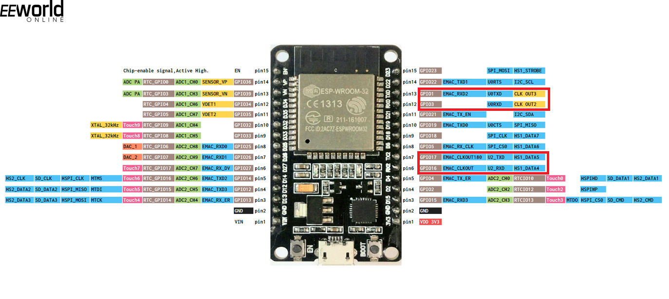
UART ports in ESP32 module
MicroPython allows multiplexing any GPIO with the hardware UARTs of ESP32. Therefore, irrespective of which default pins are exposed or not, all three UARTs can be used in a MicroPython script. While instantiating a UART object for ESP32, the Rx and Tx pins should also be passed as arguments.
Using UART in ESP8266 and ESP32
ESP8266 and ESP32 are primarily used in Wi-Fi-backed networked applications. In many of these applications, the master microcontroller managing embedded functions is another microcontroller, while ESP8266 or ESP32 plays a secondary role in handling only communication and control over the network. In such applications, UART is the only choice for data communication between ESP8266/ESP32 and the main controller of the device. Some sensors and modules may also provide a UART interface along with I2C or SPI for communicating sensor data or control signals, here again, UART in ESP8266/ESP32 can be utilized.
UART serial data communication with MicroPython
Following is a sample MicroPython script to test UART communication in ESP8266.
import os, machine
from machine import UART
os.dupterm(None, 1)
uart = UART(0, baudrate=9600)
uart.write(‘Hello’)
uart.read(5)
os.dupterm(uart, 1)
Folowing is a sample MicroPython script to test UART communication in ESP32.
from machine import UART
uart = UART(1, baudrate=9600, tx=33, rx=32)
uart.write(‘hello’)
uart.read(5)
You may also like:


Filed Under: ESP8266, Python, Tech Articles, Tutorials
Log in to leave a comment:
Lost your password?
Don't have an account? Register here