Engineers Garage

  • Projects and Tutorials
    • Electronic Projects
      • 8051
      • Arduino
      • ARM
      • AVR
      • PIC
      • Raspberry pi
      • STM32
    • Tutorials
    • Circuit Design
    • Project Videos
    • Components
  • Articles
    • Tech Articles
    • Insight
    • Invention Stories
    • How to
    • What Is
  • News
    • Electronic Products News
    • DIY Reviews
    • Guest Post
  • Forums
    • EDABoard.com
    • Electro-Tech-Online
    • EG Forum Archive
  • Digi-Key Store
    • Cables, Wires
    • Connectors, Interconnect
    • Discrete
    • Electromechanical
    • Embedded Computers
    • Enclosures, Hardware, Office
    • Integrated Circuits (ICs)
    • Isolators
    • LED/Optoelectronics
    • Passive
    • Power, Circuit Protection
    • Programmers
    • RF, Wireless
    • Semiconductors
    • Sensors, Transducers
    • Test Products
    • Tools
  • EE Resources
    • DesignFast
    • LEAP Awards
    • Oscilloscope Product Finder
    • White Papers
    • Webinars
  • EE Learning Center
    • Design Guides
      • WiFi & the IOT Design Guide
      • Microcontrollers Design Guide
      • State of the Art Inductors Design Guide
  • Women in Engineering

Obstacle Avoiding Robot

By Ashutosh Bhatt

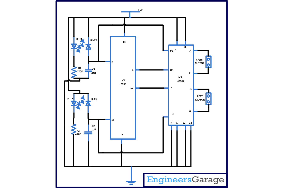
This circuit describe a simple obstacle avoiding robot which a you can easily make in your homes because it does not contains any complex digital circuitry and this can be made without using any microcontroller. This is an intelligent robot which will automatically detect the presence of obstacle in its path and change the direction of motion accordingly.

[[wysiwyg_imageupload:11703:]]

Fig. 1: Prototype of Obstacle Avoiding Robot Circuit on Breadboard


This simple circuit is based on two IC namely 7404 and L293D with few more commonly available components. In this circuit we are using IR transmitter and receiver as a sensor to detect the obstruction.

Mostly color of IR transmitter and receiver is different but sometimes color of both IR transmitter and receiver is same at that time you should be careful while using it in the circuit. If they are wrongly place than your circuit will not work. You can distinguish the IR transmitter and receiver by simple following steps with the help of multimeter.

1. First of all set the multimeter in 2M ohm range.

2. Pick one of them and connect cathode of that to positive terminal of multimeter.

3. And connect the anode with the negative terminal of multimeter.

4. Do the same with both the IR transmitter and receiver.

5. Now check the reading of multimeter.  If reading fall in the range of few hundred kilo ohms than it is an IR receiver. And if reading in the multimeter is not indicated it means it an IR transmitter. CD7404 is a NOT or inverter gate IC. in this we are utilizing only 2 gate of IC and rest are not used. To understand the working you should know about the truth table of NOT gate are as follows-


  Input        

    Output

0

1

1

0


In NOT gate we will get output as logic high when logic zero is provided and we will get logic zero when logic1 is provided in input.

CD7404 contain six inverter gates in one package as shown in diagram. In this pin 1 is input and 2 is for output  for  first gate similarly pin 3 is input and pin 4 is output for second gate similarly we have four more gate. In this 14 is for supply voltage and pin 7 is connected to ground.

edge

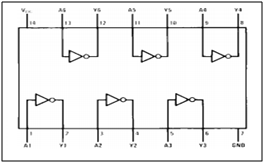
Fig. 2: Pin Diagram of CD7404

L293D- It is a motor driver IC which is used to drive the motor on either direction. L293D comes in 16 pin dual inline package. And can drive two sets of DC motor with the help of single IC which can be move independently according to the input provided. It works on the theory of H bridge which permit voltage to flow in either direction in clockwise or anti clockwise direction. Pin diagram of L293D is as follows-

edge

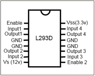
Fig. 3: Pin Diagram of L293D

From the pin diagram you can see that it has two enable pin that is pin 1 and pin 9. For rotating the DC motor enable pin should be high. For example if you want to rotate the left motor than enable pin 1 should be high. Similarly for right motor pin 9 should be high. And if any of the pin is low than that motor will not work and if both the pins are low robot will stop moving.

L293D contain four input pin 2 pin for controlling each motor. Like pin 2 and pin 7 are on left side and control the rotation of the left  motor and pin 15 and pin 10 are on right side and they control the rotation of right motor. And there outputs pin are pin 3 and 6 for left motor and pin 11 and pin 14 for right motor. Following table shown below will help to you know in which direction motor will rotate when logic 0 and logic 1 is provided on the pins.

Pin 2

Pin 7

Motor Rotation

Logic 1

Logic 0

Clockwise Direction

Logic 0

Logic 1

Anticlockwise Direction

Logic 0

Logic 0

No rotation

Logic 1

Logic 1

No rotation


Working of circuit

Assemble the circuit properly and connect power supply. Then robot will start moving on unobstructed path. When an object or obstacle come in between for example left IR sensor and receiver senses any obstacle then it has to turn right. In this case pin 2 of IC2 will become low and pin 7 become high and robot will change its direction. Similar phenomenon will happen when right IR sensor and receiver will receive the obstruction on its path to change the direction this can be seen from the table below. And if both the IR sensor and receiver sense the obstruction then both the motor will stop working as a result robot will also stop moving.

Be careful while powering the circuit as L293D works on 5V and it may possible motor you are using is working on 12V so provide a separate power supply for motors or use voltage regulator for providing power supply to IC’s.

Circuit Diagrams

Edge-avoiding-robot

Project Components

  • Capacitor
  • IC 74LS04
  • L293D
  • Resistor


Filed Under: Electronic Projects
Tagged With: obstacle avoiding robot, robot
 

Questions related to this article?
👉Ask and discuss on Electro-Tech-Online.com and EDAboard.com forums.


Tell Us What You Think!! Cancel reply

You must be logged in to post a comment.

HAVE A QUESTION?

Have a technical question about an article or other engineering questions? Check out our engineering forums EDABoard.com and Electro-Tech-Online.com where you can get those questions asked and answered by your peers!


Featured Tutorials

  • Introduction to Brain Waves & its Types (Part 1/13)
  • Understanding NeuroSky EEG Chip in Detail (Part 2/13)
  • Performing Experiments with Brainwaves (Part 3/13)
  • Amplification of EEG Signal and Interfacing with Arduino (Part 4/13)
  • Controlling Led brightness using Meditation and attention level (Part 5/13)
  • Control Motor’s Speed using Meditation and Attention Level of Brain (Part 6/13)

Stay Up To Date

Newsletter Signup

Sign up and receive our weekly newsletter for latest Tech articles, Electronics Projects, Tutorial series and other insightful tech content.

EE Training Center Classrooms

EE Classrooms

Recent Articles

  • What are the battery-selection criteria for low-power design?
  • Key factors to optimize power consumption in an embedded device
  • EdgeLock A5000 Secure Authenticator
  • How to interface a DS18B20 temperature sensor with MicroPython’s Onewire driver
  • Introduction to Brain Waves & its Types (Part 1/13)

Most Popular

5G 555 timer circuit 8051 ai Arduino atmega16 automotive avr bluetooth dc motor display Electronic Part Electronic Parts Fujitsu ic infineontechnologies integratedcircuit Intel IoT ir lcd led maximintegratedproducts microchip microchiptechnology Microchip Technology microcontroller microcontrollers mosfet motor powermanagement Raspberry Pi remote renesaselectronics renesaselectronicscorporation Research samsung semiconductor sensor software STMicroelectronics switch Technology vishayintertechnology wireless

RSS EDABOARD.com Discussions

  • Avalanche Pulser
  • Measure AC current accurateley (100mA to 10A)
  • SDR with external LO input
  • Timer MC14541B wrong delay
  • simple LSB explanation please

RSS Electro-Tech-Online.com Discussions

  • bluetooth jammer
  • Disabled son needs advice please
  • DIY bluetooth speaker
  • Someone please explain how this BMS board is supposed to work?
  • HV Diodes
Engineers Garage
  • Analog IC TIps
  • Connector Tips
  • DesignFast
  • EDABoard Forums
  • EE World Online
  • Electro-Tech-Online Forums
  • Microcontroller Tips
  • Power Electronic Tips
  • Sensor Tips
  • Test and Measurement Tips
  • 5G Technology World
  • About Us
  • Contact Us
  • Advertise

Copyright © 2022 WTWH Media LLC. All Rights Reserved. The material on this site may not be reproduced, distributed, transmitted, cached or otherwise used, except with the prior written permission of WTWH Media
Privacy Policy | Advertising | About Us

Search Engineers Garage

  • Projects and Tutorials
    • Electronic Projects
      • 8051
      • Arduino
      • ARM
      • AVR
      • PIC
      • Raspberry pi
      • STM32
    • Tutorials
    • Circuit Design
    • Project Videos
    • Components
  • Articles
    • Tech Articles
    • Insight
    • Invention Stories
    • How to
    • What Is
  • News
    • Electronic Products News
    • DIY Reviews
    • Guest Post
  • Forums
    • EDABoard.com
    • Electro-Tech-Online
    • EG Forum Archive
  • Digi-Key Store
    • Cables, Wires
    • Connectors, Interconnect
    • Discrete
    • Electromechanical
    • Embedded Computers
    • Enclosures, Hardware, Office
    • Integrated Circuits (ICs)
    • Isolators
    • LED/Optoelectronics
    • Passive
    • Power, Circuit Protection
    • Programmers
    • RF, Wireless
    • Semiconductors
    • Sensors, Transducers
    • Test Products
    • Tools
  • EE Resources
    • DesignFast
    • LEAP Awards
    • Oscilloscope Product Finder
    • White Papers
    • Webinars
  • EE Learning Center
    • Design Guides
      • WiFi & the IOT Design Guide
      • Microcontrollers Design Guide
      • State of the Art Inductors Design Guide
  • Women in Engineering