Engineers Garage

  • Electronic Projects & Tutorials
    • Electronic Projects
      • Arduino Projects
      • AVR
      • Raspberry pi
      • ESP8266
      • BeagleBone
      • 8051 Microcontroller
      • ARM
      • PIC Microcontroller
      • STM32
    • Tutorials
      • Audio Electronics
      • Battery Management
      • Brainwave
      • Electric Vehicles
      • EMI/EMC/RFI
      • Hardware Filters
      • IoT tutorials
      • Power Tutorials
      • Python
      • Sensors
      • USB
      • VHDL
    • Circuit Design
    • Project Videos
    • Components
  • Articles
    • Tech Articles
    • Insight
    • Invention Stories
    • How to
    • What Is
  • News
    • Electronic Product News
    • Business News
    • Company/Start-up News
    • DIY Reviews
    • Guest Post
  • Forums
    • EDABoard.com
    • Electro-Tech-Online
    • EG Forum Archive
  • DigiKey Store
    • Cables, Wires
    • Connectors, Interconnect
    • Discrete
    • Electromechanical
    • Embedded Computers
    • Enclosures, Hardware, Office
    • Integrated Circuits (ICs)
    • Isolators
    • LED/Optoelectronics
    • Passive
    • Power, Circuit Protection
    • Programmers
    • RF, Wireless
    • Semiconductors
    • Sensors, Transducers
    • Test Products
    • Tools
  • Learn
    • eBooks/Tech Tips
    • Design Guides
    • Learning Center
    • Tech Toolboxes
    • Webinars & Digital Events
  • Resources
    • Digital Issues
    • EE Training Days
    • LEAP Awards
    • Podcasts
    • Webinars / Digital Events
    • White Papers
    • Engineering Diversity & Inclusion
    • DesignFast
  • Guest Post Guidelines
  • Advertise
  • Subscribe

Signal and Encoding of USB System (Part 5/6)

By Amanpreet Singh May 20, 2025

In this series, USB requests and descriptors have been already discussed. With the knowledge of USB descriptors, requests, transfer types, and transactions it is now easy to understand how data is communicated over USB interface.  Another aspect of the USB communication is line states and encoding, which is generally ignored by the system designers as a USB device can be designed without knowing the Signaling and Encoding schemes. The signaling and encoding schemes are implemented at the lower levels (usually on the controller IC) and usually gets abstracted during system designing. However, understanding the terms related to bus states and encoding would help in getting a comprehensive view of the USB System.

Bus States

The Bus state refers to the signal voltage level on the USB bus or the conditions that these voltages signify -:

Differential 0 and Differential 1: The Differential 0 state refers to the condition when D+ data line is logic low and D- is logic high. The Differential 1 state occurs when D+ is logic high and D- is logic low.

Single Ended Zero: This state is also known as SE0. It occurs when both D+ and D- are logic low. The SE0 state is used by bus when entering the Disconnect, Reset and EOP (End of Packet) states.

Single Ended One: Also known as SE1. It occurs when both D+ and D- are logic high. This state can be taken as a compliment of the SE0 state. SE1 should never occur as it is an invalid bus State.

Idle: This state occurs when bus remains idle or there is no exchange of packet. For a full speed device, the voltage at D+ will be more positive than D- while for a low-speed device, the voltage at D- will be more positive than D+

Data J and Data K: Data J and K states are used to define the Data States like the Differential 0 and 1 that refers to the bus states. They are defined by Differential 0 or 1 state and the speed of the bus.

Table Listing Flip-Flop Status for Differential 0 and Differential 1 Bus States

Fig. 1: Table listing Flip-Flop Status for Differential 0 and Differential 1 Bus States


The data states are used to describe an event even when the voltages at data lines are differential. For example, a Start of Packet state exists when the bus changes from Idle to the K state.

Start of Packet: Also known as SOP. This state occurs when there is a change from Idle to K state. Every transmission of the packet begins with SOP.

End of Packet: Also known as EOP. This state occurs when SEO state occurs for two-bit times, followed by a J state for 1-bit time.

Disconnect: A downstream port at which the device is connected enters disconnect state when an SE0 state has lasted for at least 2.5 uS.

Connect:  A downstream port enters connect state when there is an Idle state for a minimum 2.5 uS and not more than 2 mS

Some Other States and Signals

Keep Alive Signal: This signal is represented by a low-speed EOP. The main motive of this signal is to keep the device in an idle state. This signal is sent at least once every millisecond, to keep the device from entering suspend state.

Suspend State: The device enters Suspend state when there is no exchange of packet or the bus remains idle for 3 mS. This state has been incorporated in USB for power conservation. In Suspended state, the device must not draw more than 500 uA of current. A suspended device must recognize the reset and resume signal.

Resume:  Resume signal is used to wake the device from Suspend state. The Host wakes the device from suspend state by keeping the bus in K state for at least 20 ms followed by a low-speed EOP.

Reset State: A device enters Reset state if SE0 is applied for more than 2.5 uS. The reset sets the device to its default unconfigured state.

Detached State: This state occurs when the USB device is detached from the Host. In this state, the Host sees both data lines low.

Attached State: This state occurs when the USB device is attached to the Host. The host recognizes this state if it sees either D+ or D- high.

Table Listing Conditions for USB Bus States

  Fig. 2: Table listing conditions for USB Bus States

Signal Diagram for Different USB Bus States

 Fig. 3: Signal Diagram for different USB Bus States

Speed Identification

In USB System, the operating speed of the device is detected by checking which data line is pulled up. The data line is pulled up to 3.3V derived from voltage line. Normally, 1.5-kilo ohm resistor is used for a pull-up.

For Low speed, D- data line is pulled up. While for full speed, D+ data line is pulled up.  High-speed devices are initially detected as full speed devices.

Encoding Scheme

The USB employs NRZI (Non Return to Zero Inversion) encoding mechanism to encode the data on the bus. In NRZI encoding, a ‘1’ is represented by no change in level while a ‘0’ is represented by change in level. Together with NRZI encoding, bit stiffing and SYNC field is used for synchronization between host and device.

Signal Diagram Illustrating Non Return to Zero Inversion (NRZI) Encoding Scheme

Fig. 4: Signal Diagram illustrating Non Return to Zero Inversion (NRZI) Encoding Scheme

Bit stiffing

When long series of zeros are transmitted using NRZI, it causes a transition in the levels. But when long series of one’s is transmitted, no transition takes place as per NRZI encoding scheme. No transition in levels for a long time can confuse the receiver and makes it desynchronized.

Bit stiffing is a process in which a zero is inserted in raw data after every six consecutive ones. The inserting of zero causes transition in level. The receiver must recognize the stuffed bits and discard them after decoding the NRZI data.

In case if no transition takes place in NRZI signal after six consecutive one’s, then the receiver decides that bit stiffing has not been done and discards the data received.
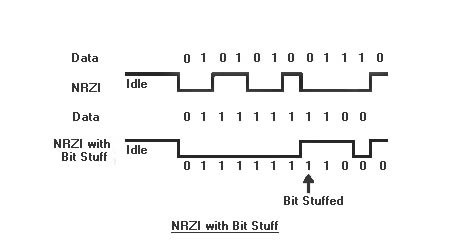
Signal Diagram showing Bit Shifting in Non Return to Zero Inversion (NRZI) Encoding Scheme

 Fig. 5: Signal Diagram showing Bit Shifting in Non Return to Zero Inversion (NRZI) Encoding Scheme 

SYNC field

The bit stiffing alone is not enough to take care of the synchronization between transmitter and receiver. To keep transmitter and receiver synchronized, SYNC field is used. In this mechanism, each packet begins with a SYNC field which enables the receiver to synchronize the clock

For low/full speed, SYNC field is of 8 bits: KJKJKJKK. The first k serves as Start of Packet. For high speed, SYNC field is of 32 bits: fifteen KJ repetitions, followed by KK. The alternate Ks and Js provide transitions for synchronizing and the final two KKs mark the end of SYNC field.

End of Packet

The End of Packet that is SE0 for 2-bit times followed by J state for 1-bit time marks the end of packet.

This is all needed to know about the signal and encoding schemes implemented in the USB system. In the final part of the series, selection of a controller chip for developing USB enabled custom devices is discussed.

You may also like:


  • Basics of Audio Amplifier – 1/9

  • What is LoRa and LoRaWAN?

  • What are the different types of EV charging connectors?

  • What are the components of robotic arms and industrial robots?

  • What are the top tools for developing embedded software?
  • brain implant
    Brain implants – Can they make the blind see?

Filed Under: Tutorials, USB


Next Article

← Previous Article
Next Article →

Questions related to this article?
👉Ask and discuss on Electro-Tech-Online.com and EDAboard.com forums.


Tell Us What You Think!! Cancel reply

You must be logged in to post a comment.

EE TECH TOOLBOX

“ee
Tech Toolbox: 5G Technology
This Tech Toolbox covers the basics of 5G technology plus a story about how engineers designed and built a prototype DSL router mostly from old cellphone parts. Download this first 5G/wired/wireless communications Tech Toolbox to learn more!

EE Learning Center

EE Learning Center
“engineers
EXPAND YOUR KNOWLEDGE AND STAY CONNECTED
Get the latest info on technologies, tools and strategies for EE professionals.

HAVE A QUESTION?

Have a technical question about an article or other engineering questions? Check out our engineering forums EDABoard.com and Electro-Tech-Online.com where you can get those questions asked and answered by your peers!


RSS EDABOARD.com Discussions

  • How to simulate a microstrip gap with such a reference plane
  • Phase Shift Full Bridge suffers spurious FET turn_ON
  • optimum spacing between feed and sub reflector
  • Equipment to see if household should buy battery/solar/inverter?
  • 'HERIC' pairs of IGBTs essential for Mains inverters

RSS Electro-Tech-Online.com Discussions

  • Epson crystal oscillators
  • Adhesive Defibrillator Pad Cable
  • Simple LED Analog Clock Idea
  • Fun with AI and swordfish basic
  • Microinverters and storeage batteries?

Featured – LoRa/LoRaWan Series

  • What is the LoRaWAN network and how does it work?
  • Understanding LoRa architecture: nodes, gateways, and servers
  • Revolutionizing RF: LoRa applications and advantages
  • How to build a LoRa gateway using Raspberry Pi
  • How LoRa enables long-range communication
  • How communication works between two LoRa end-node devices

Recent Articles

  • How to design a heart-rate pulse sensor BPM meter
  • Three-phase EMI filter with neutral provides >1 MOhm insulation resistance
  • Infineon adds 60 V and 150 V power MOSFETs with 30 krad(Si) TID and AEC-Q101 qualification
  • Microchip releases DSC families with 78 ps PWM resolution and 40 Msps ADCs
  • Silanna Semiconductor releases laser driver IC with 86% efficiency

EE ENGINEERING TRAINING DAYS

engineering

Submit a Guest Post

submit a guest post
Engineers Garage
  • Analog IC TIps
  • Connector Tips
  • Battery Power Tips
  • DesignFast
  • EDABoard Forums
  • EE World Online
  • Electro-Tech-Online Forums
  • EV Engineering
  • Microcontroller Tips
  • Power Electronic Tips
  • Sensor Tips
  • Test and Measurement Tips
  • 5G Technology World
  • Subscribe to our newsletter
  • About Us
  • Contact Us
  • Advertise

Copyright © 2025 WTWH Media LLC. All Rights Reserved. The material on this site may not be reproduced, distributed, transmitted, cached or otherwise used, except with the prior written permission of WTWH Media
Privacy Policy

Search Engineers Garage

  • Electronic Projects & Tutorials
    • Electronic Projects
      • Arduino Projects
      • AVR
      • Raspberry pi
      • ESP8266
      • BeagleBone
      • 8051 Microcontroller
      • ARM
      • PIC Microcontroller
      • STM32
    • Tutorials
      • Audio Electronics
      • Battery Management
      • Brainwave
      • Electric Vehicles
      • EMI/EMC/RFI
      • Hardware Filters
      • IoT tutorials
      • Power Tutorials
      • Python
      • Sensors
      • USB
      • VHDL
    • Circuit Design
    • Project Videos
    • Components
  • Articles
    • Tech Articles
    • Insight
    • Invention Stories
    • How to
    • What Is
  • News
    • Electronic Product News
    • Business News
    • Company/Start-up News
    • DIY Reviews
    • Guest Post
  • Forums
    • EDABoard.com
    • Electro-Tech-Online
    • EG Forum Archive
  • DigiKey Store
    • Cables, Wires
    • Connectors, Interconnect
    • Discrete
    • Electromechanical
    • Embedded Computers
    • Enclosures, Hardware, Office
    • Integrated Circuits (ICs)
    • Isolators
    • LED/Optoelectronics
    • Passive
    • Power, Circuit Protection
    • Programmers
    • RF, Wireless
    • Semiconductors
    • Sensors, Transducers
    • Test Products
    • Tools
  • Learn
    • eBooks/Tech Tips
    • Design Guides
    • Learning Center
    • Tech Toolboxes
    • Webinars & Digital Events
  • Resources
    • Digital Issues
    • EE Training Days
    • LEAP Awards
    • Podcasts
    • Webinars / Digital Events
    • White Papers
    • Engineering Diversity & Inclusion
    • DesignFast
  • Guest Post Guidelines
  • Advertise
  • Subscribe