Audio is one of the most common media. Here, It refers to the representation of sound which can be perceived by humans. Audio and Video are the essential component of any electronic media. The electronics can be used to receive audio signals (via microphone), record audio in some storage, transmit audio (through wired or wireless communication channels) and reproduce audio signals (via speakers). The audio can be represented and transmitted as either analog signals or digital signals. In this series, analog audio signals are the concern. The audio signals have a frequency range of 20 Hz to 20,000 Hz.
The loudness of an audio signal is signified by the amplitude of the signal. Like the nature of sound, the audio in the form of electrical signals also fade away with the distance. This was a major problem before the telephony engineers in the initial phase of the development of communication technologies. Typically, on a wired channel, if an electrical signal carrying audio is transmitted from one end and received at another end one mile away, it loses 90 percent of its strength. When the signal travels through a wire, the resistance of the wire causes reduction in its power (P = I2/R). The loss of signal over transmission has been a major issue before the electronic engineers. There are losses whether the signal is transmitted from just the microphone to the recording device, computer or audio generator to a speaker or it is transmitted on wire over a long distance. In order to sort out this problem, engineers devised special electronics – ‘Amplifiers’. The amplifiers increases the strength of the signal so it reaches a longer distance before diminishing. By increasing the amplitude of the input signal, basically the output power of the circuit is increased as high power signals can travel more distance than low power signals. By using amplifiers at different stages, the audio signals can then be safely transmitted over a wired connection.
Another major improvement was the representation of audio in the form of digital signals. By the representation of the audio signals in the form of digital signals, the audio data remains secured. In digital encoding, the audio data becomes independent of the amplitude of the signal and so it is not altered or lost due to noise in the cable.
In this series, analog audio signals will remain the area of concern. The digital encoding of the audio signals will not be discussed. The design and use of different kind of amplifiers will be discussed throughout this series. The following amplifier circuits will be designed in the series –
1) 250 mW Power Amplifier
2) 1W Power Amplifier
3) Bass Boost Amplifier
4) Car Audio Amplifier
5) Head Phone Amplifier
6) Stereo Amplifier
7) MAX4468 Pre-Amplifier
8) LM358 Pre-Amplifier
An Amplifier increases the strength of an audio signal by increasing its amplitude. The rise in amplitude is called Amplification. That is why, it is called Amplifier. An audio amplifier needs to be designed based on its application and required specifications. All the amplifiers listed above are designed for different applications and with different specifications as per the requirement.
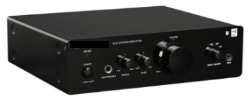
Fig. 1: Image of Typical Audio Amplifier
Understanding Audio Signals
But, before jumping over the electronics involved in the design of different amplifiers, it is important to understand the basics of audio signals, so the specifications of the amplifier circuits could be examined. The electronic devices process the sound much like the human body. The sound is produced when something vibrates in air and in turn air particles are vibrated. The vibrations are propagated through the air and received by the human ears. The ears convert those vibrations into electrical signals and send them to the brain. A microphone also does the same. In a microphone, sound waves vibrate its diaphragm which cause vibrations in other components and the vibrations are converted to electrical current forming the audio signal. This electrical signal is analog signal representing the sound. It has two important characteristics which recognize the signal as a unique sound –
1) Frequency – The frequency of the signal signifies the pitch of the sound. This is the most important factor in the recognition of a sound.
2) Amplitude – The amplitude of the signal signifies the loudness of the sound. Since, this is the voltage level of the signal at a point of time, it also represents the power of the signal. There are various ways in which the amplitude of an audio signal can be measured like Peak to Peak Amplitude, Root Means Square (RMS) Amplitude, Pulse Amplitude, Semi Amplitude etc. The Peak to Peak and RMS amplitude values will be used in the circuit analysis of the audio amplifiers designed in this series.
Peak to peak amplitude – The peak to peak amplitude is the difference in the crest (highest value of amplitude) and trough (lowest value of amplitude) of the analog signal.
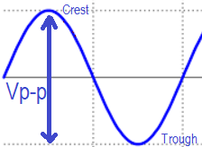
Fig. 2: Signal Diagram showing Peak to Peak Amplitude of an Audio Signal
RMS amplitude- The RMS stands for Root Mean Square. It is generally used in the context of analog signals or alternating current (AC) signals. The RMS value is the amount of current or voltage which is equal to its equivalent direct current (DC). So it is universal to define the RMS for AC signals while calculating the power in terms of DC. The following equation is used for calculating the RMS voltage from peak to peak voltage –
Vrms= Vp-p/ (2)1/2
Types of Audio Amplifiers
The audio amplifiers can be categorized in many ways. On the basis of the application of an audio amplifier, it can be categorized as follow –
1) Pre-Amplifier
2) Power Amplifier
A Pre-Amplifier is required for amplifying the very low input signals from a MIC or guitar. It is used before the power amplifier stage. These type of amplifiers do not help in increasing the output power but are used to level up the electrical signals from the Microphone or Guitar to the standard line level voltage before amplification. The output current of these amplifiers is in micro amperes, so sometimes they are also called Micro-Amplifiers. Along with voltage amplification, they also reduce the noise and distortion in the output signal. After pre-amplification, power amplifier is used to increase the output power by amplifying the current as well as the voltage of the input signal.
Audio Amplifier Characteristics
There are many design factors involved in the making of any amplifier circuit like gain, bandwidth, output power and maximum supply voltage. An audio amplifier should be designed considering all these important design factors. Some of the important design parameters involved in the making of an audio amplifier are as follow –
1) Gain – Gain is a measure of the capability of any system to increase signal power or amplitude. The gain of an amplifier circuit is expressed as the ratio of the output voltage to the input voltage (voltage gain), or ratio of the output current to the input current (current gain) or ratio of the output power to the input power (power gain). It is expressed in dB (decibel). The equation for converting the voltage gain to the gain in dB is as follow –
Gain (dB) = 20logGv
Where Gv is the voltage gain.
In the analysis of the amplifier circuits designed in this series, voltage gain will be taken as the design factor. The voltage gain is expressed as the ratio of the output voltage to the input voltage.
Voltage gain = Output voltage/ Input voltage
2. Volume and Skew Rate – The volume of an audio is determined by the output amplitude of the audio signal. As gain of the circuit decides the maximum and minimum amplitude, the volume can be changed only in the range of that amplitude only. By using a potentiometer, the amplitude of the signal can be changed and so the loudness or volume of the audio signal. An amplifier cannot suddenly change the volume of the audio signal. The maximum rate of change of the output signal is called Skew rate of the amplifier.
3. Output Power – The power output of an audio amplifier is equivalent to how loud can be sound output from it. It is generally expressed in Watts or Milli Watts. The larger will be the speakers, more output power from the amplifier will be required for them. The maximum output power of an amplifier circuit can be calculated as follow –
P = V2/2R
Where,
P = output power
V = peak to peak voltage
R = Resistance of the load
4) Linearity – In context to audio amplifiers, the linearity refers to the proportionality between input and output signal. More will be the linearity, more will be the output audio true representation of the input audio signal.
5) Bandwidth – The bandwidth refers to the frequency range in which the amplifier can operate. The amplifier circuits in this series are designed to operate within the frequency range from 20 Hz to 20 KHz.
6) Clipping Effect – The amplifier circuits are designed to have output voltages in a specific range. Usually this range is mentioned with a plus and/or minus sign. Like an amplifier may be designed to have output voltages within +/- 50V range. So, ideally the output voltage level of this amplifier will not exceed than 50V about the waveform origin. As voltage level and the power output are related, this also indicates the range of output power that can be delivered by the amplifier. If an attempt is made (by the load or speakers at the output of the amplifier) to draw more power or voltage levels than the power or voltage levels for which the amplifier has been designed, then the output waveform (carrying the audio signals) will start to clip.
By clipping, it means that the output voltage level becomes constant and equal to the maximum voltage level it can output for all voltage levels that are beyond the maximum output limit of the amplifier. As the output voltage signal is the audio signal itself, the clipping will cause distortion in the output sound. If the clipping will be severe, the output waveform can become a square wave instead of a sine wave, causing the loss of the audio signal or only noise remaining at the output of the amplifier.
Secondly, the power rating of the square wave is twice of sine wave. The power supply of most of the amplifiers cannot handle to output power twice their rated power for longer period.
Also, at the output the voltage will be practically more than the rated voltage which will cause problem at the load that is the speakers. The speakers are designed to have constant impedance. The impedance of the speakers is expressed in ohms and it is typically 2, 4 or 8 ohms. A low impedance speaker draws more power compared to a high impedance speaker. On clipping a high impedance or low power speaker can practically get damaged.
When output signal from an amplifier is clipped, it acts like constant power source or fixed DC input to the speaker inputs. The speakers have an internal coil. On getting a constant input this coil will not get a chance to cool down due to the clipping of soft passage in the audio signal. It is uncommon to blow the tweeters in the case of extreme clipping. The tweeter is a kind of speaker (dome or horn shaped) which are meant for generating the high audio frequency in range from 2 kHz to 20 kHz. The risk of damage to a speaker depends on audio signal (does it have a large amount of high frequency), the degree of clipping and how sustainable speaker is beyond its rated power. So, a speaker of high wattage and low impedance can be used with low wattage amplifier but its vice – versa is not true.
Suppose if a speaker is rated twice the amplifier output power then there will be no issues with the speaker in case of clipping. However, still the clipping will add distortion to the output audio and sound quality can be horribly reduced that no one can hang around.
So it is better to run an amplifier for an occasional clipping only as clipping increases the chances of damage to the speaker, can over stress amplifier or deteriorate the sound quality.
The clipping effect can be observed on a CRO. In the following figure, red waveform represents the supposed audio output and yellow waveform represents the clipped waveform on using an audio amplifier of lower power rating.
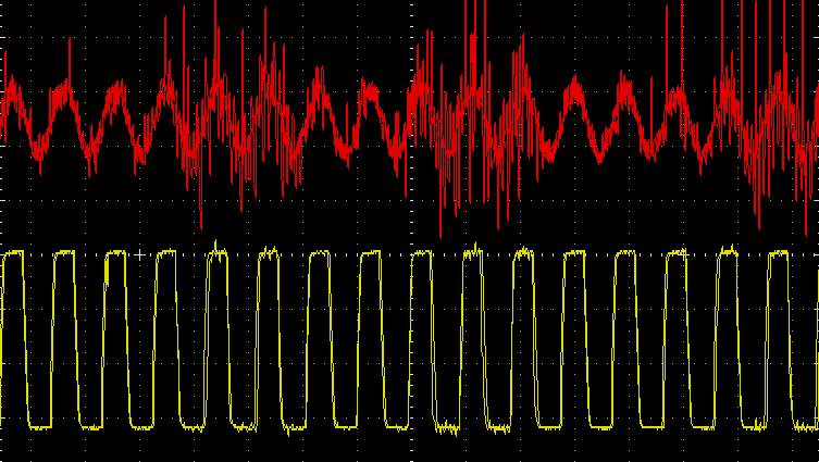
Fig. 3: Image of Waveform showing Clipping Effect on Audio Signal
7) Stability and Negative Feedback – The ability of the amplifier circuit to provide a reliable output is called stability. For increasing the stability of the circuit, negative feedback is used in the design of the amplifier circuits. There are various advantage of negative feedback like Gain stability, Noise reduction, Increase in input impedance, Decrease in output impedance and Increase in bandwidth. For providing negative feedback, the amplifier circuits in this series are designed in inverting configuration.
8) Impedance Matching – For complete power transfer from input to the output, the impedance of the source and load should be same. But it is not possible to properly match the impedance, so there is a thumb of rule that the output impedance/load impedance should be 10 times the source/input impedance. This results into a known power loss of 10% and 90% of the power is transferred to the output. So, by increasing the output impedance, the power loss of the amplifier can be greatly reduced.
9) Efficiency – The efficiency of an audio amplifier is expressed as the ratio of output power of the amplifier and the power consumed by the amplifier itself.
10) Noise and SNR – Any amplifier circuit has some noise at the output. This noise is created by the semiconductor components used in the design of the amplifier. Higher is the power output of an amplifier, more is the noise at its output. An amplifier needs to be designed so that noise at its output remains constant irrespective of the signal. Also, signal to noise ratio should remain high for the entire operating range of the amplifier. So, the amplifier must have a high Signal to Noise Ratio (SNR) which must be a constant over its operating range.
11) Harmonic Distortions – Distortions are the unwanted signals mixed with the original audio signal or input audio signal. If an audio waveform of constant frequency is applied at the input of an amplifier, it is supposed to remain the same at the output of the amplifier as well. But, frequencies of the integer multiple of the input frequency are added at the output of the amplifier. These frequencies are called Harmonic Distortions and are always the integral multiple of the input frequency. The level of distortion in the output of an amplifier is measured as Total Harmonic Distortion (THD). The Total Harmonic Distortion is the ratio of the power of all the harmonic frequencies combined to the power of the original frequency. The harmonic distortions in an amplifier must be occasional and THD for those occasional appearances too should be in tolerable limit. The THD is usually expressed in percentage. Like if an amplifier has 2 percent THD, it means that the power of all the harmonics combined is just 2 percent of the power of the original frequency. Generally, THD up to 10 percent is tolerable but it should be as low as possible. Standard Audio amplifiers have a THD as less as 1 percent or 0.5 percent.
12) Loop Grounding – In audio amplifiers, loop grounding is also one of the major problems which causes humming sound in the speakers. The different components of the amplifier are connected at different nodes of the ground. Ideally, the ground should be 0 Volts but due to resistive nature of the ground wire, it has different voltages across its length. The difference in voltage at different nodes of the ground add noise in the output audio signal. For eliminating the problem of ground loops, star topology will be used for ground and the power supply of the amplifier circuit.
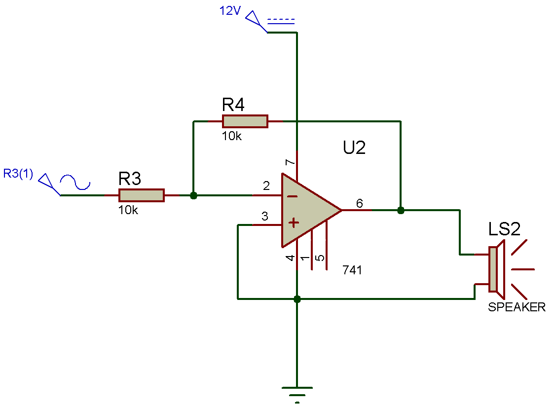
Fig. 4: Circuit Diagram of Star Topology for Ground and Supply in a Simple Amplifier
In this series, gain and output power will be mainly considered while designing the amplifier circuits.
Construction of Audio Amplifiers
An amplifier circuit can be designed using transistors or operational amplifiers. A transistor can operate in three states – Cutoff state, Active state, and Saturation state. In active state, the transistor acts as an amplifier so by configuring transistors in active state, they can be used to construct audio amplifiers. Both BJT and MOSFET can be used to design an amplifier circuit.
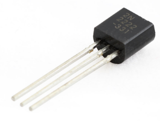
Fig. 5: Typical image of Transistor
The OPAM has basically a group of transistors connected to each other in such a way that they help in amplifying an input signal. The transistors can be used as amplifiers for simple audio systems and for more complex audio systems operational amplifiers can be used to make the audio amplifier circuit.
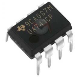
Fig. 6: Typical image of Operational Amplifier (OPAM) IC
Testing Audio Amplifier Circuits
For the testing of the amplifier circuits designed in this series, the function generator is used as the input source. The function generator is used to generate a sine wave of constant amplitude and frequency. Any audio signal is also basically a sine wave so a function generator can be used instead of using a microphone or actual audio source. So, the function generator can be used as input source for testing the audio amplifier circuits. During testing, at the output also, a speaker is not used as a load as the speaker is resistive as well as inductive. At different frequencies, its inductance changes which in turn changes the impedance (R and L combination) of the speaker. So, the use of a speaker as load at the output of the amplifier for deriving its specifications may give false or non-standard results. In place of speaker, a dummy load which is purely resistive will be used. As resistance does not change with frequency so it is sufficient to take one or two readings only.
During testing, the frequency of the signal from the function generator will be kept in range from 20 Hz to 20 KHz which is same as of the typical audio range and the observations will be taken at 26 db and 46 db gain.
For testing of the amplifier circuits, first the input voltage will be set to a desired voltage level where the input voltage should be less than the bias voltage of the transistors used in the amplifier circuits. Then, the output waveform will be observed at CRO and the input signal will be increased until the output waveform starts clipping. The Peak to Peak output voltage just before clipping will be measured for circuit analysis like determining the output power and gain of the amplifier.
Let us start making the amplifier circuits. In the next tutorial, 250 mW power amplifier will be designed.
You may also like:
Filed Under: Audio, More Editor's Picks, Tutorials





Questions related to this article?
👉Ask and discuss on EDAboard.com and Electro-Tech-Online.com forums.
Tell Us What You Think!!
You must be logged in to post a comment.