Engineers Garage

  • Electronic Projects & Tutorials
    • Electronic Projects
      • Arduino Projects
      • AVR
      • Raspberry pi
      • ESP8266
      • BeagleBone
      • 8051 Microcontroller
      • ARM
      • PIC Microcontroller
      • STM32
    • Tutorials
      • Audio Electronics
      • Battery Management
      • Brainwave
      • Electric Vehicles
      • EMI/EMC/RFI
      • Hardware Filters
      • IoT tutorials
      • Power Tutorials
      • Python
      • Sensors
      • USB
      • VHDL
    • Circuit Design
    • Project Videos
    • Components
  • Articles
    • Tech Articles
    • Insight
    • Invention Stories
    • How to
    • What Is
  • News
    • Electronic Product News
    • Business News
    • Company/Start-up News
    • DIY Reviews
    • Guest Post
  • Forums
    • EDABoard.com
    • Electro-Tech-Online
    • EG Forum Archive
  • DigiKey Store
    • Cables, Wires
    • Connectors, Interconnect
    • Discrete
    • Electromechanical
    • Embedded Computers
    • Enclosures, Hardware, Office
    • Integrated Circuits (ICs)
    • Isolators
    • LED/Optoelectronics
    • Passive
    • Power, Circuit Protection
    • Programmers
    • RF, Wireless
    • Semiconductors
    • Sensors, Transducers
    • Test Products
    • Tools
  • Learn
    • eBooks/Tech Tips
    • Design Guides
    • Learning Center
    • Tech Toolboxes
    • Webinars & Digital Events
  • Resources
    • Digital Issues
    • EE Training Days
    • LEAP Awards
    • Podcasts
    • Webinars / Digital Events
    • White Papers
    • Engineering Diversity & Inclusion
    • DesignFast
  • Guest Post Guidelines
  • Advertise
  • Subscribe

Simple Stepper Motor Driver using 555 Timer IC

By Ashutosh Bhatt September 18, 2014

The circuit presented here rotates stepper motor and varies its RPM (speed). It does not use any micro controller (or micro processor) or any programmable digital device also it does not require any software program to generate sequence of pulses. It drives stepper motor using simple, easily available and commonly used components and ICs like IC555, decade counter, OR gate, current driver chip etc. That is why the name given simple stepper motor driver.

[[wysiwyg_imageupload:13379:]]

Fig. 1: Prototype of Simple Stepper Motor Driver using 555 Timer IC Circuit on Breadboard


As shown in the circuit diagram the circuit is implemented using following chips

1.    IC555 – Used to generate sequence of pulses with variable frequency

2.    Decade Counter CD4017 – Used to divide the frequency of pulses generated by IC555 and generate different frequency pulse trains like f/2, f/4, f/8 … etc

3.    OR Gate 74LS32 – It is used to generate 4 pulse trains of frequencies f/2, f/4, f/8 and f/16

4.    Current Driver ULN2003 – Used to amplify output current of OR gates to drive stepper motor coils

IC555 is configured in astable mode. Its RC timing components are R1, R2, R3 and C1. Pot R3 is used to vary frequency of output pulses. The values are selected such that output frequency varies from 2 Hz to 3 Hz. ( the frequency variation is very low because the RPM variation is multiplied by 60 so RPM variation will be 120 to 180)

Output of IC555 is connected to clock input of counter CD4017. If input frequency is F the counter will generate 10 outputs with F, F/2, F/4, F/8 ….. likewise.

Out of these 10 outputs, 8 outputs are given as inputs to 4 OR gates of 74LS32 that they will generate only 4 outputs with F, F/2, F/4, and F/8. Like as shown in figure, 1st output is given to one input of 1st OR gate, 2nd output is given to one input of 2nd OR gate and likewise 3rd output and 4th output to 3rd and 4th OR gate respectively. 5th output is again given to second input of 1st OR gate and likewise remaining 6th, 7th and 8th outputs are given to rest of gates.

The outputs or all 4 OR gates are given to inputs of ULN2003A. ULN2003A has darlington pairs inside which drives the stepper motor coils.

Circuit Operation

The circuit operation can be explained better with the help of following waveforms.

Simple stepper motor driver Circuit Opration

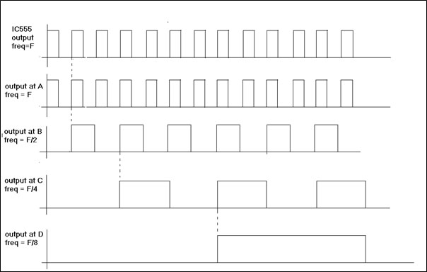
Fig. 2: Image showing  Circuit Operations in Waveform  

IC555 generates pulses at frequency F shown as 1st waveform. When it is applied to decade counter it generates 10 pulse trains of frequencies F, F/2, F/4, F/8 likewise. Because 1st and 5th output are given to 1st or gate inputs, its final output at A is of frequency F shown as second waveform. Similar to that 2nd and 6th outputs of counter are given as inputs to 2nd OR gate so its output at B will be F/2. Likewise outputs C and D are of frequency F/4 and F/8. When these outputs are given to stepper motor coils through ULN2003A chip the stepper motor will start rotating. As we change the frequency of IC555 using pot from 2 Hz to 3 Hz the RPM of motor changes from 120 RPM to 180 RPM. 


Circuit Diagrams

circuit-diagram1-1

Project Components

  • 555 Timer IC
  • Capacitor
  • LED
  • Resistor
  • ULN2003

Project Video


Filed Under: 555 Timers, Electronic Projects
Tagged With: 555 timer circuit, cd4017, IC 555, stepper motor, uln2003
 

Next Article

← Previous Article
Next Article →

Questions related to this article?
👉Ask and discuss on EDAboard.com and Electro-Tech-Online.com forums.


Tell Us What You Think!! Cancel reply

You must be logged in to post a comment.

EE TECH TOOLBOX

“ee
Tech Toolbox: 5G Technology
This Tech Toolbox covers the basics of 5G technology plus a story about how engineers designed and built a prototype DSL router mostly from old cellphone parts. Download this first 5G/wired/wireless communications Tech Toolbox to learn more!

EE Learning Center

EE Learning Center
“engineers
EXPAND YOUR KNOWLEDGE AND STAY CONNECTED
Get the latest info on technologies, tools and strategies for EE professionals.

HAVE A QUESTION?

Have a technical question about an article or other engineering questions? Check out our engineering forums EDABoard.com and Electro-Tech-Online.com where you can get those questions asked and answered by your peers!


RSS EDABOARD.com Discussions

  • connector model question
  • Color Laser printer, printing pcb layout on transparant sheet
  • Snooping Around is All
  • Industrial Relay Board Design for Motorcycle Use
  • Research on challenges in Analog Layout design

RSS Electro-Tech-Online.com Discussions

  • Faulty heat air gun (dc motor) - problem to locate fault due to Intermittent fault [unrepairable]
  • using a RTC in SF basic
  • Dismantling a WestinghouseRoku TV ?
  • Does US electric code allow branching ?
  • My Advanced Realistic Humanoid Robots Project

Featured – LoRa/LoRaWan Series

  • What is the LoRaWAN network and how does it work?
  • Understanding LoRa architecture: nodes, gateways, and servers
  • Revolutionizing RF: LoRa applications and advantages
  • How to build a LoRa gateway using Raspberry Pi
  • How LoRa enables long-range communication
  • How communication works between two LoRa end-node devices

Recent Articles

  • How IoT network topologies work
  • The top five AI startups to watch in 2025
  • STMicroelectronics unveils SoC based on secure MCU
  • Nexperia’s 48 V ESD diodes support higher data rates with ultra-low capacitance design
  • Taoglas releases Patriot antenna with 18 integrated elements covering 600 to 6000 MHz

EE ENGINEERING TRAINING DAYS

engineering

Submit a Guest Post

submit a guest post
Engineers Garage
  • Analog IC TIps
  • Connector Tips
  • Battery Power Tips
  • DesignFast
  • EDABoard Forums
  • EE World Online
  • Electro-Tech-Online Forums
  • EV Engineering
  • Microcontroller Tips
  • Power Electronic Tips
  • Sensor Tips
  • Test and Measurement Tips
  • 5G Technology World
  • Subscribe to our newsletter
  • About Us
  • Contact Us
  • Advertise

Copyright © 2025 WTWH Media LLC. All Rights Reserved. The material on this site may not be reproduced, distributed, transmitted, cached or otherwise used, except with the prior written permission of WTWH Media
Privacy Policy

Search Engineers Garage

  • Electronic Projects & Tutorials
    • Electronic Projects
      • Arduino Projects
      • AVR
      • Raspberry pi
      • ESP8266
      • BeagleBone
      • 8051 Microcontroller
      • ARM
      • PIC Microcontroller
      • STM32
    • Tutorials
      • Audio Electronics
      • Battery Management
      • Brainwave
      • Electric Vehicles
      • EMI/EMC/RFI
      • Hardware Filters
      • IoT tutorials
      • Power Tutorials
      • Python
      • Sensors
      • USB
      • VHDL
    • Circuit Design
    • Project Videos
    • Components
  • Articles
    • Tech Articles
    • Insight
    • Invention Stories
    • How to
    • What Is
  • News
    • Electronic Product News
    • Business News
    • Company/Start-up News
    • DIY Reviews
    • Guest Post
  • Forums
    • EDABoard.com
    • Electro-Tech-Online
    • EG Forum Archive
  • DigiKey Store
    • Cables, Wires
    • Connectors, Interconnect
    • Discrete
    • Electromechanical
    • Embedded Computers
    • Enclosures, Hardware, Office
    • Integrated Circuits (ICs)
    • Isolators
    • LED/Optoelectronics
    • Passive
    • Power, Circuit Protection
    • Programmers
    • RF, Wireless
    • Semiconductors
    • Sensors, Transducers
    • Test Products
    • Tools
  • Learn
    • eBooks/Tech Tips
    • Design Guides
    • Learning Center
    • Tech Toolboxes
    • Webinars & Digital Events
  • Resources
    • Digital Issues
    • EE Training Days
    • LEAP Awards
    • Podcasts
    • Webinars / Digital Events
    • White Papers
    • Engineering Diversity & Inclusion
    • DesignFast
  • Guest Post Guidelines
  • Advertise
  • Subscribe