Stepper motors are well known for their precise motion. They do not rotate continuously but they rotate in steps. That’s why they are also called digital motors. Mostly they are of low RPM with high torque. Stepper motors are widely used in
· 3 D printers
· CNC (computerized numeric control) machines
· Robotic arms
· CD/DVD/BlueRayDisk drives – players
· Accurate load positioning like rudder positioning in aircraft or ship
So stepper motors are used in almost all such fields where accuracy in motion is at most required. Some of the applications require controlling stepper motor RPM and/or direction using joystick like
· Rotating/moving a camera placed on AGV/UGV/UAV to get desire view
· Positioning a tool at desire place attached to robotic arm
· Moving items to specific place in automatic material handling system
In all such application the motion of stepper motor is controlled by joystick. So the given project demonstrates how joystick controls RPM and direction of stepper motor.
The project is build using micro controller AT89C52 and it uses simple potentiometer (pot) as a resistive joystick. As the pot is turned CW from the centre position, the motor also rotate CW and vice versa. Also as the pot is turned more CW (or CCW) the motor RPM increases. At the centre position of pot, the motor RPM is minimum. As it is turned fully CW or fully CCW, the RPM reaches to maximum in either direction.
Let us see circuit description and its operation.
Circuit Description
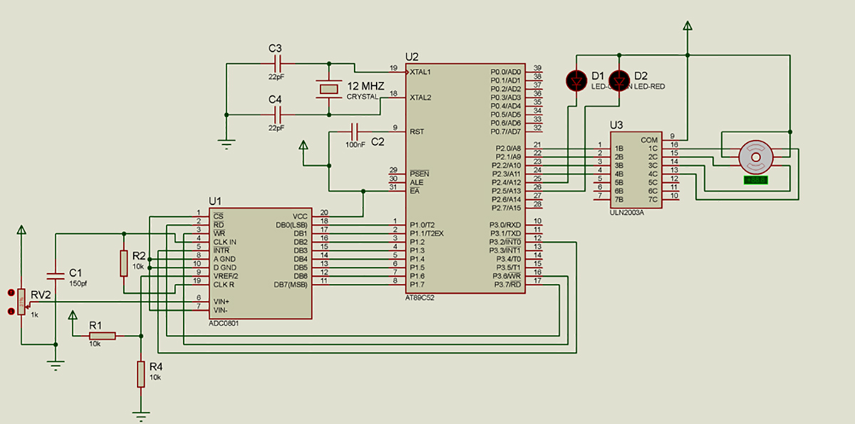
The circuit is built using three major components 8-bit ADC chip ADC0804, micro controller AT89C52 and Darlington array chip ULN2003A.
(Check the circuit diagram tab for complete circuit for Stepper motor direction and RPM control using joystick)
· The potentiometer RV2 (that works as joystick) is connected to analog input pin 6 of ADC0804 as shown. Its two fixed terminals are connected with +Vcc and Gnd
· The Vref pin (9) is given Vcc/2 (=2.5 V) volt by voltage divider network formed by R1 and R4
· R2 and C1 are connected to CLK IN (4) and CLK R (19) pin as shown that provides internal clock to ADC for conversion
· Chip select pin (1) is connected to ground to enable the chip
· Control pins RD, WR and INTR are connected with PORT3 pins P3.7, P3.6 and P3.3 of AT89C52 respectively
· Data pins DB0 – DB7 are connected with PORT1 of AT89C52
· PORT2 pins P2.0 – P2.3 drives stepper motor through darlington arrays of ULN2003A chip. These pins are connected to input of ULN2003A chip and outputs of ULN2003A chip are connected with four coils of unipolar stepper motor. Two common terminals of stepper motor coils are connected to +Ve supply
· Two LEDs – RED and GREEN are connected to P2.4 and P2.5 pins in sinking current configuration
· Capacitor C2 is connected between supply and reset pin of AT89C52 to give power on reset
· A 12 MHz crystal along with two 22pF capacitors, connected to crystal pins of AT89C52. It provides basic clock for all internal operation
Circuit Operation
· As the potentiometer slider is varied, the voltage at analog input pin of ADC varies from 0 to Vcc
· Microcontroller controls ADC operation. It sends control signals to convert this analog voltage into digital. When ADC finishes the conversion, it gives digital equivalent value to micro controller
· Micro controller checks the digital value and if its more than 128 (half of full 8-bit digital value 256) then it sends pulse sequence to rotate motor CW (clockwise) direction or else if the value is less than 128, it rotates motor CCW (counter clockwise) direction
· When motor is rotating CW, micro controller blinks RED LED and when it rotates CCW – blinks GREEN LED
· Also as the pot is turned more CW and the digital value increases from 128, the micro controller increases the frequency (that means decreases the delay) of pulses sent to motor – that will increases RPM (speed) of motor. As pot is varied linearly the frequency is also increased linearly. The RPM is maximum when pot is turned fully CW that means digital value is 255
· Again when pot is turned CCW to decrease digital value till 128, the RPM decreases linearly
· Similarly when the pot is turned more CCW and the digital value decreases from 128, the motor RPM will again increase but the motor is rotating in CCW direction
· Thus the pot works as joystick. As the pot is turned CW or CCW the motor also rotates CW or CCW and the speed on either side also increases as pot is gradually turned fully CW or CCW
The complete above operation is controlled by micro controller AT89C52. And the micro controller performs all tasks as per the program embedded into its internal memory. The program is loaded into the internal ROM (FLASH) of AT89C52 as to do following tasks
· Send write signal to ADC periodically to convert analog value into digital
· When digital value is ready, read it and check it for greater or lesser than 128
· If its lesser then rotate motor CCW and vice versa
· Also increase/decrease RPM of motor by increasing/decreasing pulse frequency given to motor

Fig. 1: Prototype of 8051 Microcontroller based Stepper Motor Joystick Controller
Project Source Code
###
#include<reg51.h>
sbit wr = P3^6;
sbit rd = P3^7;
sbit eoc = P3^3;
sbit FWD_LED = P2^4;
sbit REV_LED = P2^5;
unsigned char data d;
unsigned int t=10,fwd_flag=1;
void delay(unsigned int x) // 1 ms delay
{
unsigned int i;
TL0 = 0x26;
TH0 = 0xFC;
TR0 = 1;
for(i=0;i<x;i++)
{
while(TF0==0);
TF0 = 0;
TL0 = 0x26;
TH0 = 0xFC;
}
TR0 = 0;
}
void int1(void) interrupt 2 // external interrupt 1 service routine
{
rd = 0;
d=P1;
rd=1;
if(d>127) fwd_flag=1;
else fwd_flag=0;
if(d>0 && d<=13) t=2;
else if(d>13 && d<=26) t=3;
else if(d>26 && d<=39) t=4;
else if(d>39 && d<=52) t=5;
else if(d>52 && d<=65) t=6;
else if(d>65 && d<=78) t=7;
else if(d>78 && d<=91) t=8;
else if(d>91 && d<=104) t=9;
else if(d>104 && d<=117) t=10;
else if(d>117 && d<=127) t=11;
else if(d>127 && d<=140) t=11;
else if(d>140 && d<=153) t=10;
else if(d>153 && d<=166) t=9;
else if(d>166 && d<=179) t=8;
else if(d>179 && d<=192) t=7;
else if(d>192 && d<=205) t=6;
else if(d>205 && d<=218) t=5;
else if(d>218 && d<=231) t=4;
else if(d>231 && d<=244) t=3;
else if(d>244) t=2;
wr = 0;
wr = 1;
eoc=1;
}
void main()
{
TMOD = 0x01;
P2=0x00;
P2=0x3F;
P1=0xFF;
eoc=1;
IE=0x84;
wr = 0;
wr = 1;
while(1)
{
if(fwd_flag==1)
{
P2 = 0xEE;
delay(t);
P2 = 0xED;
delay(t);
FWD_LED=1;
P2 = 0xFB;
delay(t);
P2 = 0xF7;
delay(t);
}
else
{
P2 = 0xD7;
delay(t);
P2 = 0xDB;
delay(t);
P2 = 0xFD;
delay(t);
P2 = 0xFE;
delay(t);
}
}
}###
Circuit Diagrams
Filed Under: Electronic Projects
Log in to leave a comment:
Lost your password?
Don't have an account? Register here