Today many accidents occur because everyone is in hurry and we do not see the signal and crosses the railway line. So to solve this we can install this simple circuit which will give an red indicator when train is nearby and green indicator when train goes away from platform. For this we are using the reed switch as sensor.An indication of red and green light is done with the help LED. You can also modify this circuit to use bulb in place of LED so that it can be seen from distance.
LED Based Stop Watch
This LED based stop watches circuit can be worked as a clock in this counter will advance after every one second. When you provide power supply it start it’s counting from zero and you can stop the timer any time with the help of switch.In this circuit you can monitor the time from 1 second to 60 minutes. It can be used while cooking or while doing exercise or in laboratories. It can be used by students preparing for competitive exams. Important feature of this circuit is you can switch off the stop watch any time with the help of switch S1 and it will hold that value. Keep on reading to find out how the circuit is assembled and how it is put to use.
Reminder Alarm
Many a time it happens we forget to switch off the gas, electric oven, stove or motor while watching TV or taking on the phone or while talking to a friend in your neighborhood. To solve this problem we have described a circuit below which alarms you after the preset time interval. It will give a loud musical alarm and reminds you that you to off your machine or gas. It uses NE555 which is a well known multi-vibrator IC.Here 555 timer IC is wired as an a-stable oscillator which provide a clock pulse to CD4017 IC. CD4017 which is a medium speed Johnson Counter that works at 10MHz and has 10 decoded outputs. CD4017 ICs are widely used in frequency dividers, binary counters, and divide by N counters and register design applications.
Clock with LED pendulum with tick tock sound

Many of us see different kinds of wall clock available in market which produces sound but they are very expensive. The circuit described here produces a tick tock sound and also indicate the time with the help of LED. In this circuit, LED’s are arranged such that you will get time in the form of a pendulum first in one direction than in opposite direction. So you can make your own watch in much less price as compared to market.This simple circuit is based on two IC’s namely NE555 timer and CD4017 with few more discrete components. 555 timer IC wired as an a-stable oscillator. In this circuit NE555 a-stable generates a clock for the Circuit, which provide a oscillating wave to the output pin 3 of IC1. You can vary the speed of oscillation with the help of R2.
Parked Vehicle Indicator
Some time at night it happens that we have to park our vehicle at highway because of some emergency and it may possible another speeding vehicle rams into another vehicle parked at the edge of highway. Mostly cars have flashing indicator, but heavy vehicle like trucks, buses and auto rickshaws have no such kind of indicator or warning flasher present. Here we have described a simple fleshing circuit which will be visible from a distance and warn the vehicle driver. This simple circuit is based on NE555 timer. In this circuit 555 timer is working in a-stable mode.In this mode 555 timer work as free running oscillator means it does not have any permanent or steady state and it is continuously changing its state from low to high and come back to its original state. This continuous switching from one state to another state from high to low and low to high produces a continuous square wave at output.
Spell Effect Sign Display Circuit
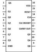
In speller effect sign display each letter will be highlighted one after the other and the cycle is repeated until power supply is provided. This circuit can be used in shops or restaurants to display the name or phone number. This circuit is useful in night to highlight the name of restaurant, which will attract the customer. The circuit is based on two IC’s namely NE555 and CD4017 with few more components. In this circuit NE555 a-stable generates a clock for the circuit, which provides an oscillating wave to the output pin 3 of IC1. CD4017 is a 16 pin CMOS decade counter/ Divider. It take clock signal from the clock input and turn on the 10 output in sequence, each time when it receives clock input pulses. It is the most popular IC and extremely useful in various project like Light Chaser, Matrix Die. In order to understand the working of IC one must know about its individual pin. It has 3 input pin and 10 output pin and one is ground pin and another is used for power supply and one is Carry out pin.
Electronic Circuit: Digital Stopwatch
This circuit can be worked as a clock in this counter will advance after every one second. When you provide power supply it start its counting from zero and you can stop the timing with the help of switch. It can be used while cooking or while doing exercise. It can used by students preparing for competitive exams. You can also use this circuits during playing game like teams have to complete the task and the team which have done it in shortest period of time first will be the winner. In such type of game we can easily record the time of individual team. In this the team which finishes the task just has to flip the switch S2 and time gets recorded. This circuit also calculates the time in minute. In this circuit when 99 seconds completed a musical sound is heard and it will sound till 50 seconds and stop again for approx. 40 seconds.
DIY- Heart Shape LED Light Flasher
Ever wanted to gift something “Electronically Special” to your loved ones? This article will show you how to make such gift in an Engineer’s style. All we need is a 555 Timer IC and a couple of other electronic components to make this LED Heart Flasher.Basically, the 555 Timer IC is made to work as an “Astable Multi-vibrator” here. We need at least 12 LEDs to make the shape of a heart and a 555 IC is not capable of directly driving 12 LEDs at a time. So that is why we have used a medium power transistor 2N3019 which can drive loads up to 1 Ampere. The transistor works as a switch here and the output from the 555 IC provides the switching signal to the transistor. We’ll be driving the circuit using 6 volts.And one more advantage of this circuit is that you can customize the frequency and Pulse width of the signal by changing the value of the resistors and capacitors
Timer Based Code Lock

Nowadays various kinds of code locks are available in the markets which are very costly. The Code lock described here is an electronic combination lock which can be used in daily life. The circuit is described here has following main advantages: You can use 16 switches or more to make it more confusing and people will think you have used a microprocessor, there is no need to amplify signals hence no need of transistor, low cost and small in size and switch has to be pressed in specific interval of time to open the lock.The circuit is built around a single IC that is NE555 timer which works in mono-stable mode. In mono-stable mode IC is once trigged it will hold the output for a specific interval of time as defined by the timing component before returning to its original state.
Timer Circuit using IC 4026

The circuit can be used as a clock. In this circuit the counter will advance after one minute or after every one second depending on the value of resistor selected. It can be used while cooking or while doing exercise or by students preparing for competitive exams.This circuit is based on NE555 and CD4026, which is a Johnson counter IC commonly used in digital display. It has a 5 stage Johnson decade counter with decoder which converts the Johnson code to a 7 segment decoded output. It means input will be converted into numeric display which can be seen on 7 segment display. It can be used in various applications like in 7 segments decimal display circuit, in clocks, timer etc. Read more to find out how the circuit is built and how it works.
Number Guessing Game

The number guessing game is quite simple. In this game the player thinks any number between 1 to 99 and then if same number is displayed on screen, he wins otherwise player looses the game. This simple circuit is based on two IC’s namely NE555 which is a timer IC. In this circuit we are utilizing it astable mode. And another one that we are using is 4026, which is a decade counter/divider IC. It converts the input into numeric display without any decoder IC which can be seen on 7 segment display. In this circuit NE555 astable generates a clock for the circuit, which provides a oscillating wave to the output pin 3 of IC1. The time period of counter can be calculated by following formula T = 0.7 (R1 + 2*R2)*C1.
Random Number Generator Using 7 Segment Display
It is very simple and easy to construct project which will display random numbers from 0 to 7 on a 7 segment display. This circuit can serve as an alternative that can be used to replace the traditional dice while playing games such as snake ladder, monopoly etc. It uses NE555 which is a well known multivibrator IC. Here 555 timer IC is wired as an astable oscillator which provide a clock pulse to CD4017 IC.CD4017 which is a medium speed Johnson Counter that works at 10MHz and has 10 decoded outputs. CD4017 ICs are widely used in frequency dividers, binary counters, divide by N counters and register design applications and CD4511 which is a BCD to 7 segment decoder.
9-Way Clap Switch Circuit Diagram
With the help of this circuit you can control your home appliances without getting off from your bed. You have to just clap or puff in front of the microphone and the device connected to it become “on” or “off”. Features of this circuit are :- You can simultaneously “on” and “off” one, two or three devices.. You are not required to move from your place to “on” or “off” the devices.When you clap in front of the Mic, clapping sound is converted into electrical energy by the microphone. These weak signals are then amplified by the transistor which acts as preamplifier. Sensitivity of the signals can be improved with the help of VR1. Now the transistor T1’s output is feed to monostable circuit which is wired NE555 IC. Whenever you clap in front of microphone, output pin 3 of IC1 goes high and this is fed to clock input of IC2 pin 14.
Bathroom Light Off Timer
In this circuit 555 timer is wired as one shot timer whose timer period can be easily calculated by- T=1.1*R1*C1 Where T is in seconds, R is in ohms and C is in farads. When anybody wants to use the bathroom, it will press the switch momentarily. As soon as switch is pressed, relay connected…
IC555 based Multicolor LED Lamp Circuit Diagram
NE555 astable generates a clock for the circuit, which provides an oscillating wave to the output pin 3 of IC1. You can vary the speed of oscillation with the help of VR1. The frequency of oscillation of 555 timer can be calculated by: f=1.44/(R1+2*(VR1)*C1) Now this wave is supplied to CD4017 decade counter pin 14…
Wireless Switch Circuit Diagram
Normally, home appliances are controlled by means of switches, sensors, etc. However, physical contact with switches may be dangerous. The circuit [[wysiwyg_imageupload::]]described here requires no physical contact for operating the appliance. You just need to move your hand over the light dependent resistor (LDR). The device connected to it switches “on” when you put your hand over the LDR and remains “on” until you again move your hand over it.The circuit is based on two ICs: one is operational amplifier LM741 and JK Flip Flop CD4027. An op-amp produces an output voltage that is hundreds of thousand times larger than the voltage difference between its input terminals. CD4027 is a master slave JK flip flop IC which works in toggle mode. Here this IC can be used to change the state by the signal applied to one or more control inputs and will have one or two outputs. CD4027 has four inputs namely J, K, Set and Reset and it contain two outputs namely Q and Q bar (Q not).
Water Sensor Circuit
This circuit is very sensitive to trigger and activate the audio visual alarm when wetness is sensed at its probes. This project is useful at homes to detect the water [[wysiwyg_imageupload::]]supply in the situations when the timing of water supply is not fixed. This circuit uses the 555 timer along with some sensor element which can detect moisture.In this circuit based project, 555 timer works in astable mode. It is driven by the emitter current which is coming from BC548 transistor as this transistor has high gain. In astable mode IC 555 functions as an oscillator. So for 555 to work in full oscillator mode a high current is required so as to trigger it. As the probes sense the moisture on it, the transistor gets switched ON and small current starts flowing between the base and the emitter. When no moisture is detected i.e. in dry state it remains OFF.
Single switch motor on/off.. Clockwise/anticlockwise
Shown here is an easy to construct electronic circuit through which a motor can be made to run in both directions i.e. clockwise and anticlockwise. An interesting [[wysiwyg_imageupload::]]fact that adds to the curiosity of the circuit is that this is done by pressing a single switch. This project finds a good application in areas of robotics. The commonly used H-Bridge circuit uses two control signals to control both the directions of the motor. Before we begin explaining the circuitry, let’s have some information about the H-Bridge circuit.H Bridge CircuitMainly used to control DC motors and stepper motors, H-bridge divides the voltage on the either side of the load. In this circuit, two IC555 timers form the H-bridge circuit around the motor. These 555 timers work in astable mode. Let’s find out more about how the circuit works.
IC 555 Based Message Display Circuit
Here is a simple circuit that displays a “HAPPY NEW YEAR” message. The alphanumeric display can be fitted anywhere in your home .The circuit is built around [[wysiwyg_imageupload::]]555 ICs, twelve KLA511 common-anode alphanumeric displays(IC1 to IC12) and a few discrete components. IC 555 functions as timer circuit and message is displayed for two minutes which is pre-determined by making the 555 work into monostable multivibrator mode. In this mode, one state of 555 based timer has a fixed duration, while other state surfaces up only when an interrupt is witnessed.KLA511 displays are a popular category of alphanumeric LED displays that consume low power and can work for longer duration without generating excess amount of heat. Each KLA511 unit comprises of 7 LEDs and has a common-anode circuit arrangement which along with some passive components, gives optimized display outputs. Keep on reading to find out how the circuit is constructed and what makes it work.
NE 555 Timer based Automatic Headlight
Automatic headlamp is very useful for miners as it eliminate the need to manually switch the headlamp ON and OFF while entering into the mines where light is [[wysiwyg_imageupload::]]not sufficient. The circuit described below works as a human eye to outside light levels and independently turns on and off the lights when needed .It hence offers both safety and convenience. This circuit is very helpful when you are entering into a tunnel at twilight or sunlight even in foggy and rainy condition. For example when you enter into a dark tunnel you will not have to search for headlight switch it will automatically turn on after sensing the poor quality of light and when you come out from tunnel it will turn off automatically.The headlamp circuit is based on NE555, which is widely known to generate accurate timing pulses. Being a multivibrator IC, NE555 works in monostable and astable mode.