555 timer IC is very commonly used to produce time delays in monostable mode. The IC produces a time delay every time its trigger pin 2 is given an active low signal. The time of the delay is decided by the value of resistance and capacitance. However, in many applications it is required to trigger 555 whenever the output goes high. This circuit based project addresses to the aforesaid problems. The circuit in this project uses an npn transistor T1 to achieve the above objective. 555 timer in monostable configuration is shown in the figure. Pin 2, which is the trigger pin of the IC is connected to the collector of T1. Continue reading to find out how the circuit is connected and how it works.
Sound generation in audio range using 555 timer
This simple project can be used to generate sound which can be heard through a speaker or a buzzer by connecting either of them to its output. The idea is to [[wysiwyg_imageupload::]]generate a frequency in the audible range from a normal pulse generator. Using the circuit in a battery saving mode so that it can work for a longer duration is made possible by using a 555 IC. This IC is known to work in three different modes: bistable, astable and monostable, and can work efficiently in all three modes. Also, being casted in an integrated circuit format makes 555 a power efficient and it can be stretched to work for a longer duration. Read more to find out how the circuit is constructed and how it works.
Intruder alarm / Burglar alarm based Home Security System
This electronic device is designed to alert the user to an intrusion. The project consists of a sensor and a control unit which are connected to each other. The [[wysiwyg_imageupload::]]sensor detects the interruption whenever an object or person comes between its transmitter and receiver. This interruption results in a signal generation which is supplied to a speaker. This way whenever an intrusion takes place, the speaker goes on. Such devices are installed at various locations in houses or offices, especially near doors, windows.In this project, the transmitter part of the circuit is an Infrared (IR) Led which transmits continuous IR rays to be received by IR receiver. The reception of rays at IR receiver results in high voltage at the output. The output of this IR sensor remains low when no signal is received. Keep on reading to find out how the circuit is constructed and what makes it work.
Long range IR using transistor and 555 timer astable mode
The commonly used IR transmitter has a limited range. This circuit based project can be used to increase its range. This is achieved by amplifying the signal [[wysiwyg_imageupload::]]which is fed to the IR Led for transmission.Major function in assisting IR LED to increase its range is carried out by two devices: BC 547and a NE555 Timer.BC 547 is a NPN transistor which is generally used in common emitter configuration for switching and amplification purposes. In the circuit, the transistor works in its usual configuration and is using a voltage divider procedure for biasing.NE555 is a popular 555 timer used for several applications as it generates pulses of accurate width. It can be operated in monostable and astable modes.
Operating Device using TSOP1738 based IR transmitter and receiver & relay

Operating an electrical/electronic device through wireless communication is very commonly required and seems very interesting. The circuit of the project [[wysiwyg_imageupload::]]described here can operate such appliances. A few salient features of the circuit are shown below:1. The circuit mainly comprises of a transmitter and a receiver component.2. Whenever a signal is received by the receiver, it activates a switch which in turn turns the appliance on.3. In this project, the transmitter component of the circuit is basically an Infrared (IR) Led which is configured to emit rays at a frequency of 38 kHz. For this purpose, NE 555 timer is used in astable mode.
Fire alarm using temp sensor (LM35), opam (LM339) & 555 timer IC
At times we forget to switch off our heating devices and eventually they get damaged. Therefore there is always a need of a device which can alert by sounding [[wysiwyg_imageupload::]]an alarm if the device temperature goes beyond a particular value. Same concept can be used in this project about fire alarm. If a building catches fire then it will raise an alarm and people could evacuate the building. This circuit uses a LM35 temperature sensor along with a LM339 comparator. Interfaced to LM339 are the following components: Resistors, Capacitors, Transistors, 555 Timer, Buzzer (output). This project about fire alarm circuit is based around LM35 which is a temperature sensor and could be used to switch an alarm when temperature goes beyond a preset value. In this circuit the output of LM35 is fed to the negative pin of comparator of LM339. The positive input is connected to a preset VR1 of value 10K.
Traffic light signal using 555 timer in astable mode
This project describes the functioning of the traffic light system, which are commonly used on the streets. In this circuit 555 timer is used to produce a clock [[wysiwyg_imageupload::]]pulses, which are used by a counter to produce the required output. Mentioned below are a few interesting facts about this circuit:· The 555 timer is used in its astable mode.· Besides 555 IC, a 4017 IC which is CMOS decade counter is also used in this circuit.· A bypass capacitor too is used in the circuit. Read more to find out how the circuit can be constructed and how it works.
Metronome using astable mode of 555 timer IC
The circuit based project describes an electronic metronome, which produces toc-toc sound at regular time intervals. Metronome is popular as a synchronizing tool [[wysiwyg_imageupload::]]for musicians through which they can match the tempo of their beats and hence, perform better. Known to be a greek invention, metronome breaks into two terms: metron which means measure; and nomos which decodes to “law”. Metronome has been a mechanical invention which, with advancement in time, has come to be electric and even software based. Explained here is an electronic circuit that works as a metronome.The metronome circuit uses 555 timer IC at its heart along with a few passive components and a speaker that works as an output device for the metronome.
Darkness detector using LDR and astable mode of 555 timer IC
This circuit based project demonstrates the principle and operation behind the darkness detector. For example lamps which switch on automatically in the night. [[wysiwyg_imageupload::]]Various decoration lights are needed to be switched on automatically in dark. The circuit described here is more of a sensor application with a speaker attached to it as output. However, depending upon the application, user can attach a night lamp or series of small LEDs to the circuit too. Constructed around a 555 timer IC and LDR, this circuit uses a 9V battery as a power source along with a couple of passive circuit components: resistance and capacitance. In this circuit 555 works in astable mode producing a frequency of about 56 hertz. Keep on reading to find out how the circuit is assembled and how it works.
Light detector using LDR and astable mode of 555 timer
Many a times we need a device which should activate itself according to outside light (like when we open door of drawer it should lit up). We sometimes feel the [[wysiwyg_imageupload::]]need of some light activated device, such a device could be made from circuit presented here. This light detector circuit project uses a light sensitive element which activates the circuit in light and switches it off in absence of light.The light detector project presented here can be used in these applications: Such circuit can be used in refrigerators to automatically switch their light on or off corresponding to the status of door of refrigerator .It could be used as morning alarm, which switches on with morning sunlight. In drawers and wardrobes, on opening their door some light should automatically switch on.
Parental Control
Children like to watch cartoons movies or any other their favourite show on the television and do not pay attention on their studies even at the time of examination. So to keep eye on children we have design a parental control device. When the children in your home hold the remote of the television to on the TV or want to change channel and press any button of the remote then a loud sound would be generated by the device. And these will let you know that your child has tried to switch on the TV. The main advantage of these circuit is that you can easily do your work without any trouble as it produces loud noise so you can hear the noise while working in the kitchen or while sitting in the nearby room.
Simple DC Motor Controller using 555 Timer IC

Controller is actually a combination of two circuits – driver circuit and Switching circuit. Driver is the actual circuit that drives DC motor and switching circuit decides how DC motor should be driven. So actually, switching circuit is the main circuit that controls the motor. Now there are two parameters of DC motor that can be controlled Speed and Direction.Changing the direction of DC motor is very simple just reverse the supply given to DC motor. For varying speed of motor you have to vary the applied DC voltage. One well known method widely used in industries is Pulse Width Modulated (PWM) speed control of DC motor also known as chopper control.
FM Remote for Toycar
This is very much interesting application and I think you will surly build it. Any battery powered toy car can be made to run or stop from a remote place (around 100 mts) using this remote. Because it is RF remote you can operate your toy car through the obstacles (like wall, partitions etc.). So it…
Timer Operated Relay with Digital Display
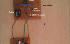
The circuit presented here operates a relay for Fixed Timer Interval. So the device or machine connected with relay operates for same time. The device once switched ON, automatically switches OFF after Fixed (set) Time Interval when relay switches OFF. The Time Interval can be varied and it is displayed on 7 Segment Display. This kind of circuits can be used in many applications where it is required to operate any device or machine for Fixed Time Interval. Like· The Alarm Signal (or Bell) once triggered, remains ON for Fixed Time Interval and then shuts off automatically· In Manufacturing Industries the Motors have to be rotated for Fixed Time Interval once start button is pressed. It stops automatically when time period is overTime operated relay circuit is build using IC555. To display the time period in seconds 2-digit decade counter is build using CD4026 chip. Another IC555 is used to provide 1 Hz pulse to update time period after every 1 sec.
Automatic water level controller

Water level controllers are quite common nowadays. This circuit is based on popularly used IC555 IC. Water level controller circuits have these advantages: Mostthe circuit only display the amount of water present in circuit, but this circuit will “on” and “off” the motor according to the level of water present in tank. It will not automatically stop the motor when tank is fill but it will “on” the motor when water in tank reaches below a specific point. It can be easily installed in over headed tanks because of less components used in circuits. It prevents the wastage of water due to over flow of tank. Can be operated with the help of 12V battery or adaptors (converts 230V AC to 12V DC) readily available in markets.