Abstract: – In most of the industrial processes it is required to rotate DC (or AC) motor forward and reverse for desired time. First motor rotates forward (clockwise) for some time (say 2 – 3 min) then it stops for some time. Again it rotates reverse (anticlockwise) for some time and rests. This process repeats every time when gets triggered.
For example, in automated bottle filling plant, the bottles are moving on conveyor belt. When it comes under filler, the filler comes down (that means motor attached with mechanism rotates forward) then it fills the bottle (that means motor stops). Again it goes up (motor rotates reverse) and stops. As the next bottle arrives, the same process is triggered again. For moving filler up and down the time of rotating motor forward and reverse is calibrated and fixed. Also the motor stop time is calibrated based on time required to fill the bottle. Another very good domestic application is washing machine. Once timer is set to wash cloths the motor automatically rotates forward and reverse for fixed time (10 – 15 sec) with small pause in between. So I can give thousands of such applications where there is a need to run motor forward – stop – reverse – forward…. and so on.
Now because this is sequential process we can use sequential timer. Sequential timer is widely used circuit in industries because in most of the industries all the processes are of chain reaction type. That means one process ends and it triggers next. The last process triggers first process when it ends. And thus the cycle continues. These sequence timers are micro controller based multi-functional and programmable. But here I have developed a sequential timer using simple IC555. So let us see how it is done
Here the process is of three steps (forward-stop-reverse), I have used three stages of IC555 connected in cascaded to form 3-stage sequential timer.
· 1st stage – rotates motor forward
· 2nd stage – stops motor
· 3rd stage – rotates motor reverse
These stages actually energize or de-energize relays that connect motor with the supply. Let us see the block diagram of this sequential timer controlled DC motor.
Video
Video
Block Diagram
System Block Diagram: –
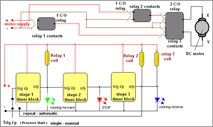
The complete system consists of 3 blocks of IC555 connected in cascaded. The output of each stage is connected to trigger input of next stage. The output of 1st stage drives single change over (1 C/O) relay 1 and output of 3rd stage drives 2 relays simultaneously. One is 1 C/O relay and another is 2 C/O relay. The 2nd stage output do nothing. They just provide delay in between 1st stage and 3rd stage outputs. a green LED connected at the 1st output indicates direction of rotation is forward and blue LED at the 3rd stage indicates motor rotates in reverse direction. the red LED in the middle stage indicates motor is stop.
The trigger input is given to 1st stage every time to start the process. The process finishes as motor rotates forward – stops – reverses. Again when it is required to repeat the process, The trigger input is applied. If switch is placed on repeat automatic position, the last stage o/p is given as input to first stage. So the process repeats in continuous loop.
As shown in figure, The 3 relay contacts are connected in such a way that they provide reversible supply to motor.
· When relay 1 gets energizes its contacts provides supply to motor in such a way that motor terminal ‘X’ becomes +Ve and terminal ‘Y’ becomes -Ve. So motor rotates in one direction (clockwise)
· When relay 2 and 3 are energized simultaneously their contacts provides supply to motor in such a way that motor terminal ‘X’ becomes -Ve and terminal ‘Y’ becomes +Ve. So motor rotates in another direction (anti clockwise)
Working and operation: –
1. Initially when circuit supply and motor supply both are switched on, the output of all the IC555 are low and all the relays are off. So motor will not get supply and it is stop
2. Now when trigger input is applied to 1st stage, its output goes high the relay energizes and motor rotates forward. The time period for which motor rotates can be determined by the RC time components of timer.
As time period finishes output goes low and relay de-energizes. So motor stops.
5. Now 1st stage triggers 2nd stage that actually does nothing. It just provides delay till its output goes low depending upon timing components.
6. As 2nd stage output goes low, it triggers 3rd stage and its output goes high. This stage energizes two relays simultaneously. This will rotate motor reverse.
8. Again as the time period finishes, 3 rd stage output goes low and motor is again disconnected from supply and stops.
9. If process has to be repeated trigger input is applied again. In repeat mode the third stage output again triggers first stage. So motor will start rotating forward.
Now let us see the design of each timer block in detail.
1st stage timer block
1st stage timer block: –

It’s very simple circuit. IC555 is connected in monostable mode with timing components R1, R2 and C1. Its output drives 6 V 1 C/O relay coil through NPN transistor 2N2222A (Q1). Also green LED1 is connected with output. Same output is coupled to next stage through coupling capacitor C2. Depending upon timing component value let us calculate maximum time period and minimum time period
Tmin = 1.1 × R2 × C1
= 1.1 × 47× 103 × 2.2 × 10-3
= 114 sec = 2 min aprox
Tmax = 1.1 × (R1+R2) × C1
= 1.1 × (470× 103 +47 × 103) × 2.2 × 10-3
= 1251 sec = 21 min (aprox.)
This means you can rotate motor from minimum 2 min to maximum 20 min. One can always change this max time and min time limits by changing timing component values as per requirement.
2nd stage timer block
2nd stage timer block: –

The only change in design of this block is value of timing components. Because, this block does nothing and provides only delay in between 1st stage and 3rd stage. Only a red LED is connected is connected at the output to indicate motor is stop. The output is coupled to 3rd stage through coupling capacitor C4. Stop time is comparatively less. That’s why the value of timing components are less.
Tmin = 1.1 × R2 × C1
= 1.1 × 120× 103 × 470 × 10-6
= 62 sec = 1 min
Tmax = 1.1 × (R1+R2) × C1
= 1.1 × (470× 103 +120 × 103) × 470 × 10-6
= 310 sec = 5 min (aprox.)
So motor stop time is limited to 5 min. Usually stop time requirement is less in terms of 1 to 5 min. but if process requires more time then increase the values of timing components.
3rd stage timer block
3rd stage timer block: –

The timing component values of this block are similar to 1st stage as forward rotation time and reverse rotation time should be same. The difference is, this stage drives simultaneously 2 relays using NPN type Darlington pair Q2 – Q3 as shown in figure. Both relay coils are connected parallel. The Darlington pair provides enough current two energize both relays. A blue LED connected at the output indicates change in direction of rotation of motor. Again the output is coupled to first stage using coupling capacitor C6. This may be required if the process has to be repeated continuously in loop.
This completes the design of DC motor direction control using sequential timer made using simple IC555. As I said earlier it has lots of industrial applications so one can design and use it as per requirement.
Filed Under: Electronic Projects

Questions related to this article?
👉Ask and discuss on Electro-Tech-Online.com and EDAboard.com forums.
Tell Us What You Think!!
You must be logged in to post a comment.