Engineers Garage

  • Electronics Projects and Tutorials
    • Electronic Projects
      • Arduino Projects
      • AVR
      • Raspberry pi
      • ESP8266
      • BeagleBone
      • 8051 Microcontroller
      • ARM
      • PIC Microcontroller
      • STM32
    • Tutorials
      • Audio Electronics
      • Battery Management
      • Brainwave
      • Electric Vehicles
      • EMI/EMC/RFI
      • Hardware Filters
      • IoT tutorials
      • Power Tutorials
      • Python
      • Sensors
      • USB
      • VHDL
    • Circuit Design
    • Project Videos
    • Components
  • Articles
    • Tech Articles
    • Insight
    • Invention Stories
    • How to
    • What Is
  • News
    • Electronic Product News
    • Business News
    • Company/Start-up News
    • DIY Reviews
    • Guest Post
  • Forums
    • EDABoard.com
    • Electro-Tech-Online
    • EG Forum Archive
  • DigiKey Store
    • Cables, Wires
    • Connectors, Interconnect
    • Discrete
    • Electromechanical
    • Embedded Computers
    • Enclosures, Hardware, Office
    • Integrated Circuits (ICs)
    • Isolators
    • LED/Optoelectronics
    • Passive
    • Power, Circuit Protection
    • Programmers
    • RF, Wireless
    • Semiconductors
    • Sensors, Transducers
    • Test Products
    • Tools
  • Learn
    • eBooks/Tech Tips
    • Design Guides
    • Learning Center
    • Tech Toolboxes
    • Webinars & Digital Events
  • Resources
    • Digital Issues
    • EE Training Days
    • LEAP Awards
    • Podcasts
    • Webinars / Digital Events
    • White Papers
    • Engineering Diversity & Inclusion
    • DesignFast
  • Guest Post Guidelines
  • Advertise
  • Subscribe

89S51/52 ISP Programmer – Basics

By Himanshu Choudhary December 26, 2011

 
Everyone in their daily life has been using microcontrollers knowingly or unknowingly embedded in machines like cars, TV, refrigerator, washing machine, etc. Many of you know the capabilities of microcontrollers and have worked with it. You should have programmed it using different programmers by manufacturers. Have you ever thought how does a programmer work? What is the basic principle behind it? Why do we have different programmers for different chips? In this series of tutorials we will try to get answers of such questions. We will do all the operations which are done by a programmer like read, write, erase etc. one by one. We will work with the 89S51 microcontroller belonging to the 8051 family. The same methodology can be used to program other members like 89S52 & 89S53 microcontrollers.
 
A programmer, also called as a burner, is a device which is used to feed a program in a microcontroller. It consists of a hardware and software. The software reads the hex file generated by the compiler and feeds it into the target microcontroller. For more details about the programmer, refer the tutorial on Microcontroller Programmer/Burner.
 
In this series of tutorials, we will perform every function a programmer performs one by one. We will not use any software but rather use two controllers. One is the target controller on which every operation will be performed and the second controller will be the master controller which will have the necessary codes to perform the different functions of a programmer. The objective of this exercise is to understand the concepts behind the working of a programmer and learn to design a programmer from scratch. If you are good at software designing you can design the software also for the programmer using any language.
 

Programming a microcontroller
In this particular article we will learn to erase the target microcontroller. The details about programming any microcontroller is given in datasheet. Datasheet discloses every minute detail about programming a controller. It tells about all the ways in which a programmer can be programmed, the circuit, the pins to be used, the signals and timing etc. There are generally two methods of programming a microcontroller
 
1.      Parallel programming
2.      Serial programming
 
In Parallel programming bits are transferred in multiple of 8 therefore one byte at a time. We have different address bus, data bus and control signal. Bus is collection of wires through which data is transmitted from one part to another. In this process we latch data on data bus, address on address bus and control signal are applied. As the control signals are applied data and address are accepted by the controller and data is stored in their corresponding position according to address. This method has become obsolete as the hardware needed for this method is quite complex and bulky.
 
In Serial programming single bit is transferred at a time using ISP protocol therefore Serial programmers also called ISP programmers. The hardware needed is very simple and small. There is no need to take out the target microcontroller from the circuit. ISP programming requires 6 pin of the target microcontroller (including Vcc and GND).
 
1.      Vcc (Pin No. 40): Connected to +5V supply.
2.      GND (Pin No. 20): Connected to Ground.
3.      RESET (Pin No. 9): Made high (1). It tells the target controller that it is under the programming mode.
4.      SCK (clock pin, Pin No. 8): This pin is used to supply clock to the target microcontroller.
5.      MISO: Master In Slave Out (output pin, Pin No. 7): This is the output pin of the target microcontroller which sends the acknowledgement signals to the master controller.
6.      MOSI: Master Out Slave In (input pin, Pin No. 6): This is the input pin of the target microcontroller. Every signal including data, address and control are received on this pin of the target microcontroller.
 
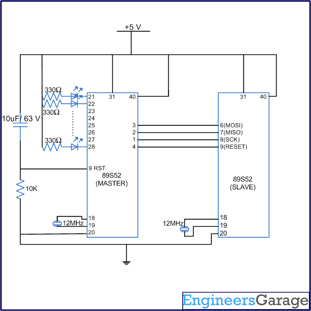
The circuit diagram for programming the target microcontroller using a master controller is shown below.
 
Circuit Diagram of 8051 Programmer

Fig. 1:  Circuit Diagram of 8051 Programmer

Please note while programming an 89SXX series of microcontroller the pin number of the target microcontroller are fixed and not of the master microcontroller. It is not necessary to use the MOSI, MISO and SCK pin of the master controller. Any pin could be used for the purpose. However for the target controller it has to be MOSI, MISO and SCK only.

 The first step is to dump any program in the target microcontroller using a programmer. Now the objective of this tutorial is to write a code in the master controller to erase the target microcontroller. 
 

Instruction Sets

Instruction Sets (Byte pattern):
Circuit Diagram of 8051 Programmer

Fig. 2:  Table listing 8051 instructions to perform different operations during the programming process

The above table shows the instruction sets used to perform different operations during the programming process. Every instruction is made up of 4 bytes. When a particular instruction is received by the target microcontroller, the corresponding operation is performed.
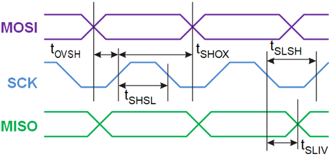
 Every byte in an instruction set consists of eight bits. Every bit needs to be sent serially to the target controller. Let us first see as to how a single bit is sent to the target microcontroller in the programming mode.
 
The bit (data or address) to be sent is always received on the MOSI pin of the target microcontroller i.e., MOSI is the input pin of the target microcontroller. The MISO pin behaves as the output pin of the target microcontroller i.e., it sends the acknowledgement and other output signals from the target microcontroller to the master controller. It behaves as input to the master controller. The SCK pin is used to provide clock to the target controller from the master controller.
Signal Diagram of MOSI, SCK and MISO pins while flashing 8051 Microcontroller
Fig. 3: Signal Diagram of MOSI, SCK and MISO pins while flashing 8051 Microcontroller
Serial Programming Characteristics, TA=  – 40OC  to 85OC, VCC = 4.0V – 5.5V
Symbol
Parameter
Min
Typ
Max
Units
1 / tCLCL
Oscillator Frequency
3
 
33
MHz
tCLCL
Oscillator Period
30
 
 
ns
tSHSL
SCKPulseWidth High
8tCLCL
 
 
ns
tSLSH
SCKPulseWidth Low
8tCLCL
 
 
ns
tOVSH
MOSISetup toSCK High
tCLCL
 
 
ns
tSHOX
MOSIHold after SCKHigh
2tCLCL
 
 
ns
tSLIV
SCKLow to MISO Valid
10
16
32
ns
tERASE
Chip Erase Instruction Cycle Time
 
 
500
ms
tSWC
Serial Byte Write Cycle Time
 
 
64tCLCL+ 400
µs
 
The above diagram shows how a single bit of data is sent and received from the target microcontroller. The following is an algorithm to send a bit from the master to the target microcontroller.
 
1.      Make SCK low.
2.      Load the bit to be sent on the MOSI pin.
3.      Make SCK high. When SCK goes from low to high the bit is received by the target microcontroller.
4.      The SCK should remain high for the duration mentioned in the figure above.
 

Codes for various operatiions

The code  to send a bit from the master to the target microcontroller.
sck=0;
bit=byte/128;
byte=byte<<1;
mosi=bit;
sck=1;
delay(1);
_nop_();
sck=0;
delay(1);
_nop_();

In order to send the next bit the same process is repeated.

 
Whenever the target microcontroller receives a bit during the programming mode, it acknowledges the receipt of the bit by sending an acknowledgement bit on the MISO pin, which should be received by the master controller. The algorithm for receiving the bit by the master is:
 
1.      Make SCK high.
2.      Make the input pin of the master controller active to take input from the MISO pin.
3.      Make SCK low.
 
If you carefully look at the timing diagram the transmission and reception of a single bit can be completed in a single clock cycle. The timing for the high and low pulse of different signals (MOSI, MISO and SCK) has been given in the table above.
 
The code to receive a single bit is as follows:
sck=1;
delay(1);
_nop_();
data=data<<1;
if(miso==1)
	data++; 
sck=0;
delay(1);
_nop_();


Codes Contd..


The following is the code to send and receive a single bit to and from the target controller:

sck=0;
bit = byte/128;
byte=byte<<1;
mosi=bit;
sck=1;
delay(1);
_nop_();
data=data<<1;
if(miso==1)
	data++; 
sck=0;
delay(1);
_nop_();

Now let us see how an entire byte comprising of eight bits is sent and received serially to and from the target microcontroller.

Signal Diagram showing bytes transferred through MOSI, SCK and MISO pins while flashing 8051 Microcontroller
 Fig. 4: Signal Diagram showing bytes transferred through MOSI, SCK and MISO pins while flashing 8051 Microcontroller
 
The above timing diagram shows how a byte is sent and received serially. A careful observation shows that when the transmission and reception of a single bit is repeated 8 times a byte will be transferred and received from the target microcontroller. The important point to be noted is the most significant bit (MSB) of the byte in sent and received first.
 
The algorithm for transmission and reception of a single byte using the serial ISP mode is as follows.
 
1.      Extract the MSB from the data to be sent by dividing by 128. In this case the data to be sent is stored in the variable “byte”.
2.      Left shift the byte to be sent by 1 so that the next significant bit becomes the MSB.
3.      Load the bit on the MOSI pin of target microcontroller.
4.      Make SCK 1.
5.      Provide a delay of 30 ms.
6.      The acknowledgement data coming from the target microcontroller is received in the variable “data”.
7.      Left shift the variable “data” by 1 so that the MSB which is going to be received from the target microcontroller can be received. 
8.      Check the MISO pin of target microcontroller. If it is “1” increment the data variable by 1.
9.      Make SCK 0.
10. Provide a delay of 30 ms.
11. Repeat the steps 1-10 eight times to send and receive 1 byte.
 
 The code for the sending and receiving a single byte is as follows:
sck=0;
for(i=0;i<8;i++)
{
	bit = byte/128;
	byte=byte<<1;
	mosi=bit;
	sck=1;
	delay(1);
	_nop_();
	data=data<<1;
	if(miso==1)
		data++; 
	sck=0;
	delay(1);
	_nop_();
}


Filed Under: Tutorials
Tagged With: 8051, isp, microcontroller
 

Next Article

← Previous Article
Next Article →

Questions related to this article?
👉Ask and discuss on Electro-Tech-Online.com and EDAboard.com forums.


Tell Us What You Think!! Cancel reply

You must be logged in to post a comment.

EE TECH TOOLBOX

“ee
Tech Toolbox: Internet of Things
Explore practical strategies for minimizing attack surfaces, managing memory efficiently, and securing firmware. Download now to ensure your IoT implementations remain secure, efficient, and future-ready.

EE Learning Center

EE Learning Center
“engineers
EXPAND YOUR KNOWLEDGE AND STAY CONNECTED
Get the latest info on technologies, tools and strategies for EE professionals.

HAVE A QUESTION?

Have a technical question about an article or other engineering questions? Check out our engineering forums EDABoard.com and Electro-Tech-Online.com where you can get those questions asked and answered by your peers!


RSS EDABOARD.com Discussions

  • i need an embedded c program that will read a 12 bit memory address from the io pins and output the data to pins from the memory in a 8051 mcontroller
  • DIY Buck Boost Converter using XL6019
  • Getting Started with Electronics: What Helped You the Most in the Beginning?
  • De-embedding using Y, Z parameter
  • Simple Active Bandpass Filter Oscillates

RSS Electro-Tech-Online.com Discussions

  • 12v battery, 18v magic
  • parallel-to-serial problem
  • STM32 checking self-written delay function
  • Behringer MX 1602 mixer - reading block diagram
  • Reclaiming missing motherboard header

Featured -USB Series

  • Controller Chip Selection for Developing USB Enabled Device (Part 6/6)
  • Signal and Encoding of USB System (Part 5/6)
  • USB Requests and Stages of Control Transfer (Part 4/6)
  • USB Descriptors and their Types (Part 3/6)
  • USB Protocol: Types of USB Packets and USB Transfers (Part 2/6)
  • Introduction to USB: Advantages, Disadvantages and Architecture (Part 1/6)

Recent Articles

  • Littelfuse driver achieves less than 1 µA standby current for energy-efficient designs
  • Microchip optimizes power consumption in transceiver-less FPGA design for automotive applications
  • What is an IoT platform and when is one useful?
  • Silanna launches laser driver IC with sub-2 ns FWHM pulse for LiDAR application
  • LEM introduces current sensors with bandwidth up to 2.5 MHz for precision applications

EE ENGINEERING TRAINING DAYS

engineering

Submit a Guest Post

submit a guest post
Engineers Garage
  • Analog IC TIps
  • Connector Tips
  • Battery Power Tips
  • DesignFast
  • EDABoard Forums
  • EE World Online
  • Electro-Tech-Online Forums
  • EV Engineering
  • Microcontroller Tips
  • Power Electronic Tips
  • Sensor Tips
  • Test and Measurement Tips
  • 5G Technology World
  • Subscribe to our newsletter
  • About Us
  • Contact Us
  • Advertise

Copyright © 2025 WTWH Media LLC. All Rights Reserved. The material on this site may not be reproduced, distributed, transmitted, cached or otherwise used, except with the prior written permission of WTWH Media
Privacy Policy

Search Engineers Garage

  • Electronics Projects and Tutorials
    • Electronic Projects
      • Arduino Projects
      • AVR
      • Raspberry pi
      • ESP8266
      • BeagleBone
      • 8051 Microcontroller
      • ARM
      • PIC Microcontroller
      • STM32
    • Tutorials
      • Audio Electronics
      • Battery Management
      • Brainwave
      • Electric Vehicles
      • EMI/EMC/RFI
      • Hardware Filters
      • IoT tutorials
      • Power Tutorials
      • Python
      • Sensors
      • USB
      • VHDL
    • Circuit Design
    • Project Videos
    • Components
  • Articles
    • Tech Articles
    • Insight
    • Invention Stories
    • How to
    • What Is
  • News
    • Electronic Product News
    • Business News
    • Company/Start-up News
    • DIY Reviews
    • Guest Post
  • Forums
    • EDABoard.com
    • Electro-Tech-Online
    • EG Forum Archive
  • DigiKey Store
    • Cables, Wires
    • Connectors, Interconnect
    • Discrete
    • Electromechanical
    • Embedded Computers
    • Enclosures, Hardware, Office
    • Integrated Circuits (ICs)
    • Isolators
    • LED/Optoelectronics
    • Passive
    • Power, Circuit Protection
    • Programmers
    • RF, Wireless
    • Semiconductors
    • Sensors, Transducers
    • Test Products
    • Tools
  • Learn
    • eBooks/Tech Tips
    • Design Guides
    • Learning Center
    • Tech Toolboxes
    • Webinars & Digital Events
  • Resources
    • Digital Issues
    • EE Training Days
    • LEAP Awards
    • Podcasts
    • Webinars / Digital Events
    • White Papers
    • Engineering Diversity & Inclusion
    • DesignFast
  • Guest Post Guidelines
  • Advertise
  • Subscribe