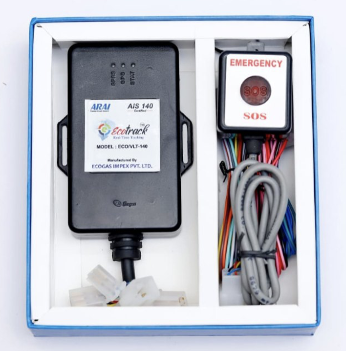
The persistent states include powered off, booting, cellular-searching, cellular-registered, TCP-connected-and-logged-in, PVT-transmitting, emergency-active and buffering-offline. The device won’t enter every state during every trip. The emergency-active state, in particular, is rare during normal operation and can only be cleared by an authorized backend command.
Event triggers include power on from the ignition or backup battery cutover, cellular registration success or failure, TCP connection success or failure and GPS fix acquisition or loss. Other triggers include the expiration of PVT and health timers, a panic button press or line cut, a tamper event, a backend command, an ignition-off transition, main power loss and an EO (Emergency Off) command from the backend.
Each event causes an outgoing packet, updates the device’s internal state or does both. The protocol uses four primary transmission types, including login, PVT, health and emergency packets, along with a command-reception type that follows a fixed grammar. The complexity comes from determining when each packet is sent, which fields it contains, which IP endpoint receives it and what transmission cadence applies.
The protocol primarily uses TCP/IP for transport. Some backends also support UDP as an alternative, while SMS can serve as a fallback for backend-to-device commands and the activation process. The base standard requires the device to support at least two IP addresses simultaneously. Emergency packets must be sent to both the primary regulatory PVT endpoint and the secondary emergency response endpoint. This provides a second delivery path if one endpoint is unreachable.
Depending on the implementation, the device may use two parallel TCP sockets or one TCP socket and a separate UDP path.
With that structure in mind, here’s what happens when a driver turns the key.
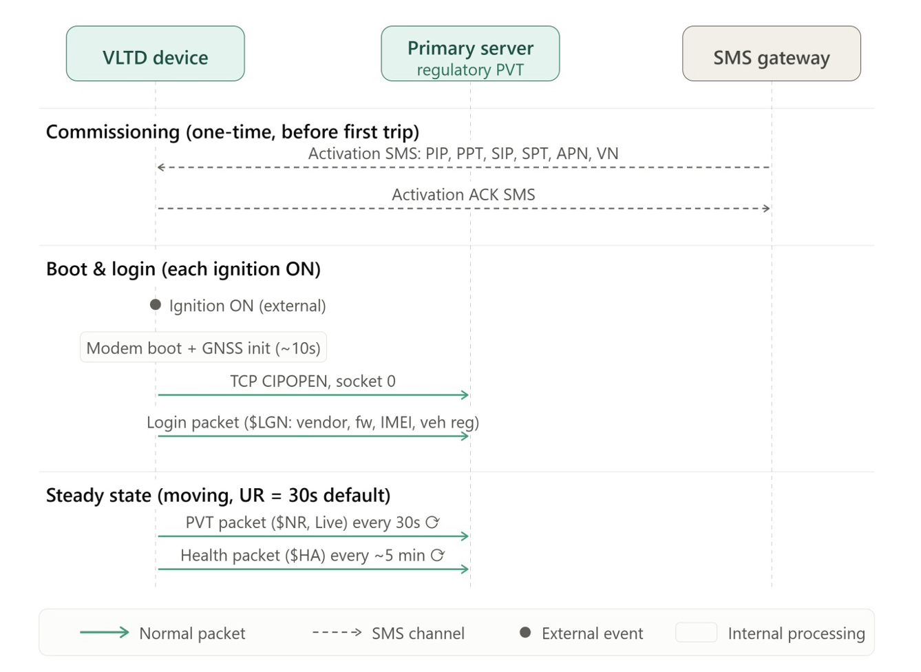
When a commercial vehicle with an AIS-140 VLTD starts up, the device receives a power-on event. Depending on the installation, the ignition line may switch on and supply the device from the main 12 or 24-V rail. If the device is already running on backup battery, the ignition line can instead go high without changing the main power state. The two paths lead to different behavior later, but the firmware follows the same initial startup sequence.
The microcontroller boots first. On an ESP32-based prototype, this can take a fraction of a second. On an STM32 device with an automotive-grade bootloader, startup may take longer if it includes authenticated firmware verification. The firmware then initializes the required peripherals. It configures UART communication with the cellular modem and I2C communication with the accelerometer. It also initializes the GPIO for the panic button and tamper switch, the ADC for voltage sensing and the non-volatile filesystem used for the store-and-forward buffer.
The firmware then powers on the cellular modem. Modules such as the SIMCom A7672S or Quectel EG91 require a specific PWRKEY sequence, typically a rising edge held for about one second before release. Depending on the module and firmware, the internal boot process can take several seconds to around 15 seconds before the modem is ready to accept AT commands. During this period, the device doesn’t transmit anything.
Once the modem is ready, the firmware runs an initialization sequence using AT commands. It typically disables echo, enables verbose error reporting, checks the SIM, configures the APN and attaches to the network. If the modem uses its internal GNSS, the firmware also enables the GPS engine. This isn’t part of the AIS-140 protocol itself. The cellular link setup must succeed before AIS-140 traffic can flow.
The device then waits for cellular registration. It polls AT+CREG?, or an LTE-specific equivalent such as +CEREG?, until the modem reports registration on the home network or a roaming network. With good coverage, registration can take only a few seconds. In poor coverage, such as a bus at a depot in a building’s basement, it may take a minute or longer and can sometimes require AT+COPS to force network selection. During this process, the device remains silent at the AIS-140 protocol layer.
Once the modem registers with the network, the firmware opens a TCP connection to the primary server. The server IP address and port come from the device’s persistent configuration, which was written during commissioning. At the AT-command layer, this can look like AT+CIPOPEN=0,”TCP”,”<PRIMARY_IP>”,<PRIMARY_PORT>. If the connection succeeds, the modem returns a positive result code and the socket is ready.
At this point, AIS-140 protocol traffic begins.
The first packet the device sends over every new TCP connection is the login packet. This isn’t optional. The protocol requires the device to send a login packet whenever it establishes or re-establishes a connection with the server. The login packet identifies the device and vehicle to the backend. Without it, the backend can’t associate subsequent PVT packets with a registered vehicle.
At minimum, the login packet carries the vendor ID, a manufacturer-assigned identifier, the firmware version, the cellular module’s 15-digit IMEI and the vehicle registration number. Some state variants use a header such as $LGN, while others use $Header,LGN,… or a similar format. The frame ends with a * delimiter, a two-character hexadecimal XOR checksum calculated over the payload and a \r\n line terminator. The QuecPython reference implementation exposes this as send_login(**login_kwargs).

On the backend, the login packet associates the TCP socket with the vehicle. If the IMEI is unknown because the device hasn’t been commissioned, the backend typically closes the socket. If the IMEI is recognized but the vehicle number doesn’t match the existing association, the backend may log the discrepancy and either accept or reject the login according to the state’s policy. Under normal conditions, the backend accepts the login, registers the socket internally and places the device in the logged-in state.
At this point, the device may or may not have a GPS fix because GPS acquisition occurs independently of the TCP connection process. With a clear view of the sky, the device may acquire a fix before login completes. During a cold start, especially if the receiver hasn’t had a recent satellite fix, acquisition can take 30 to 60 seconds even with a NavIC-capable receiver.
The firmware doesn’t wait for a GPS fix before sending the login packet. Instead, it marks the GPS fix status as invalid in subsequent packets until a valid fix becomes available.
Steady state: the PVT loop while driving
Once logged in, the device enters its main operational loop, which is dominated by the periodic transmission of PVT, or Position, Velocity and Time, packets. This is the workhorse of AIS-140. Everything else is either an event that occurs alongside this loop or a variation of its transmission cadence.
Three parameters govern the cadence. UR is the Update Rate, URE is the Update Rate Emergency and URH is the Update Rate Health. The QuecPython reference lists all three as recognized SET keys. During normal operation, only UR applies to the PVT loop.
In many state deployments, the device transmits every 30 seconds while the vehicle is moving and no more frequently than every ten minutes when the ignition is off. Some deployments use intervals as short as ten seconds while the vehicle is moving. The exact cadence depends on the applicable state implementation and backend requirements.

A single PVT packet is not small. It carries a comma-separated list of fields that describe the vehicle’s kinematic state and the device’s operational context.
Based on the field descriptions in the state protocol documents, a typical PVT frame contains a header identifying it as a PVT packet, the vendor ID, firmware version, a packet status flag for Live or History data, the IMEI, vehicle registration number and a GPS fix validity flag.
The packet also contains the current UTC date in DDMMYYYY format and the current UTC time in HHMMSS format. Position data includes latitude, latitude direction, longitude and longitude direction. Depending on the implementation, the coordinates may use decimal degrees or DDMM.MMMM format. The packet also reports speed in km/h, heading in degrees, the number of satellites in view, altitude in meters, PDOP, HDOP and the network operator name.
Additional fields describe the device’s operational and network status. These include the ignition status, main power status, main voltage, internal battery voltage, an emergency status flag, a tamper alert flag and GSM signal strength in dBm. The packet also carries the MCC, MNC, LAC and cell ID. Some variants include neighbouring cell IDs and LACs. Digital input and output status as bitmasks, a monotonically increasing frame number and a checksum complete the frame.
The checksum is an NMEA-style XOR of all bytes between the $ header and the * delimiter, encoded as two hexadecimal characters. Some state variants use a decimal checksum instead of hexadecimal, so this detail should be verified against the applicable backend protocol.
The frame status flag for Live or History data is a subtle but important field. When the device sends a packet in real time as the PVT timer expires, it sets the flag to L for Live. When the device flushes a previously buffered packet from non-volatile storage, it sets the flag to H for History. This tells the backend that the data is old and should be logged for historical playback rather than treated as the vehicle’s current position. The frame number also helps the backend identify gaps and reorder history packets that arrive out of sequence.
The device sends each PVT packet to the primary server over the existing TCP socket. At the AT-command level, it uses AT+CIPSEND with the payload length, followed by the payload bytes. The modem then returns +CIPSEND: 0,<reqSendLength>,<cnfSendLength>, where 0 identifies socket 0.
The transmission succeeds when the requested and confirmed byte counts match. If they don’t match, or if the modem reports a send failure because the TCP connection has dropped, the firmware treats the packet as unsent and moves it to the buffer instead of immediately retrying the transmission.

Concurrent with the PVT loop, the health packet timer runs at the URH cadence. The default URH in most deployments is around five minutes. When the timer fires, the firmware constructs a health packet and sends it to the same primary endpoint.
The health packet uses a different header code, often $HA or $HLM depending on the variant. It includes the vendor ID, firmware version, IMEI, main voltage and backup battery voltage. It also reports a low-battery flag, the currently effective UR and URE values, digital input and output states and diagnostic bits for the device’s internal state. The Vahan Suraksha protocol describes this as a “Regular health check of the device fitted on the vehicle as per the parameters and frequency defined in below Table 3B.”
The backend uses health packets to populate its device health dashboards and generate “device silent” notifications for vehicle owners. The standard defines thresholds of one, three, or seven days, and 30 days of silence. As the silence period increases, the backend escalates the notifications and downstream compliance flagging. A VLTD that’s physically disconnected in a workshop and forgotten can therefore become a compliance problem for the vehicle owner fairly quickly.
While the PVT loop is running, the device is also listening. The TCP socket is bidirectional, so the backend can send commands to the device at any time. In the SIMCom AT command implementation, incoming data arrives as +IPD<length> following +RECV FROM:<IP>:<port> URCs by default in direct-push mode. When the socket uses buffer-access mode through AT+CIPRXGET=1, incoming data arrives as +CIPRXGET: 1,<link_num> URCs. The firmware reads the incoming payload and dispatches it to the command handler.
The panic button flow

The panic button is the highest-priority event the device handles. Everything else pauses for it. It’s also the flow where the protocol’s design choices show most clearly. The button is normally closed, the emergency state is cleared by the server and the alert is delivered to two endpoints. Each of these choices exists for a specific reason.
The hardware side of the panic button is a normally closed pushbutton wired to microcontroller GPIO configured as an input with a pull-up resistor. In the resting state, the button is internally shorted, so the GPIO reads low because the button pulls the input to ground. When the button is pressed, its contact opens, the GPIO’s internal pull-up wins and the input reads high. Crucially, cutting the wire between the button and the microcontroller has the same effect as pressing the button. The pull-up drives the input high. This is deliberate. It means an attacker can’t silence the panic function by cutting its cable.
When the GPIO transitions high, the microcontroller fires an interrupt. The interrupt service routine does minimal work. It sets a flag and returns. The main firmware loop then observes the flag on its next iteration, debounces the input, typically over 50 to 100 ms of consistent high readings to filter mechanical bounce, and if the debounce confirms a genuine press, transitions the device into the emergency-active state.
The transition into emergency does five things. First, it sets the emergency flag in the internal device state. This flag is persistent and survives a reboot. Even if the device is power-cycled during an emergency, on the next boot the firmware reads the persistent emergency flag and comes up in emergency mode.
Second, it changes the PVT transmission cadence from UR to URE. URE is commonly set to around five seconds, versus 30 seconds for normal PVT. The exact default varies by state deployment and is set by the backend at commissioning. The tighter cadence gives emergency responders a fresher position stream.
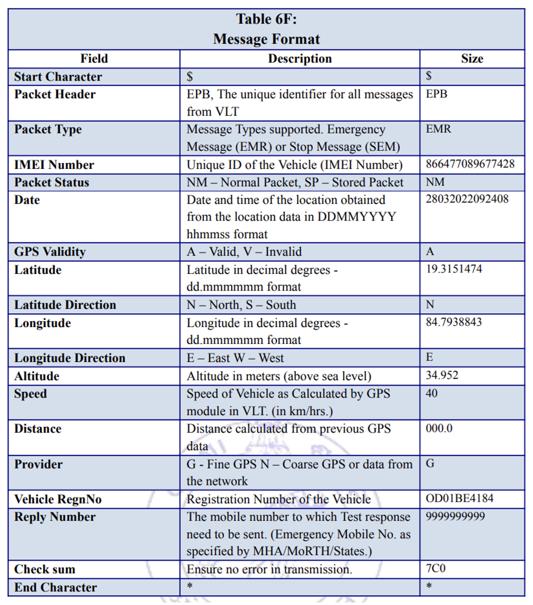
Third, it constructs an emergency packet. The emergency packet is structurally similar to a PVT packet, but with the header code changed, typically $EA for Emergency Alert or $Header,EA,…, and the emergency flag set. All other fields are the same as a normal PVT packet, including current location, speed, heading, timestamp, IMEI and vehicle registration.
Fourth, it delivers that packet to the primary IP endpoint, the regulatory PVT server, and the secondary IP endpoint, the emergency response server. The Odisha protocol PDF explicitly requires this dual delivery for emergency alerts. It specifies that the device must support at least two IP addresses, one for regulatory PVT data and one for the emergency response system, in addition to any IP addresses required for operational purposes. This dual delivery protects against a single backend being unavailable when an emergency occurs. The two mandated IPs are in addition to any operational IPs the manufacturer uses for its own fleet-management backend, not instead of them.
Fifth, it activates the local indicators. The emergency LED stays solid or blinks rapidly, and the buzzer sounds on devices that include one. These local indicators serve two purposes. They confirm to the passenger that the panic button was recognized, and they act as a deterrent because a visibly alerting device is harder for an attacker to ignore.
The Odisha PDF also states that the device continues sending emergency packets until the emergency server disables emergency mode. This is the critical detail about how emergency mode ends. The device never clears its own emergency state. Not on button release, not on reboot and not on network reconnect. The only thing that clears the emergency state is a specific command from the backend.
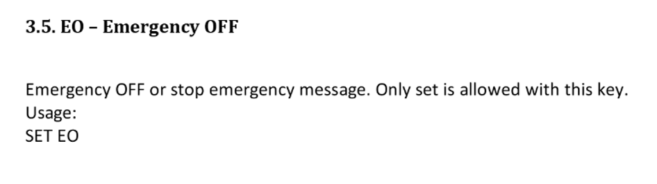
That command is EO (Emergency OFF). The QuecPython command reference lists it as one of the recognized SET keys. When the emergency response operator confirms the incident is over, typically after police dispatch and physical arrival at the scene or after determining that the trigger was a false alarm, they issue an EO command from the emergency backend to the device.
The device parses the command, clears the emergency flag, transitions back to the PVT-transmitting state at the normal UR cadence, deactivates the local emergency indicators and returns to normal operation.
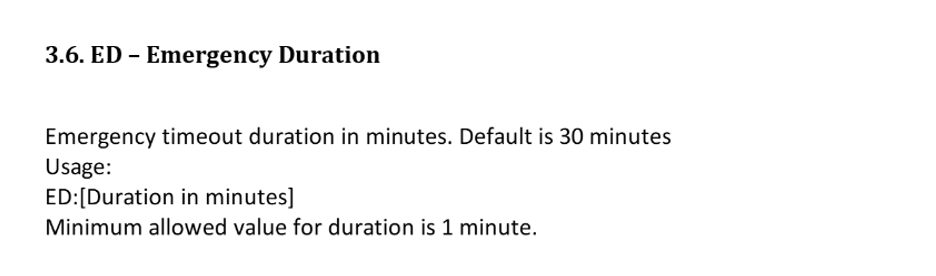
Some implementations also support an ED (Emergency Duration) command, which is also listed in the QuecPython reference. This lets the backend set a maximum emergency duration, after which the device auto-clears the emergency state if no EO has been received. In state variants that use ED, this acts as a safety net if the backend loses contact with the device. The device won’t stay in emergency mode forever. The ED value varies. In some deployments, it’s set to a value long enough to allow time for human involvement, often several hours. In others, it’s tighter.
Between the emergency onset and the EO clearing command, the device continues to send emergency packets at the URE cadence. If the TCP link drops during an emergency, those packets get buffered like any other, with the emergency flag still set. When the link comes back and the device flushes its buffer, those emergency packets are marked as history but still arrive at the emergency backend, where they’re processed as post-hoc emergency data rather than live alerts.
There’s a subtle interaction between the panic flow and the two-IP requirement worth calling out. In a device with only one open TCP socket, the primary, the emergency packet still has to get to the secondary. Implementations handle this differently.
Some open a second TCP socket at commissioning and hold both open for the device’s lifetime. Others open the secondary socket only when the emergency triggers, sending the emergency packet on both sockets during the emergency and closing the secondary when EO is received. The choice affects cellular data usage and reconnection behavior. The standard is agnostic to which approach you use, as long as the emergency alert is delivered to both endpoints.
Part 2 will continue the AIS-140 protocol walkthrough by examining how the VLTD responds when normal operation is interrupted, from backend intervention and connectivity loss through ignition-off and end-of-trip behavior.
You may also like:



Filed Under: Tech Articles
Log in to leave a comment:
Lost your password?
Don't have an account? Register here