In the previous tutorial, we discussed analog output in the form of PWM signals when using Arduino. We generated a PWM wave from Arduino by employing the analogWrite() function that approximates to a rectified sine wave. It, then, uses that analog output to fade an LED.
A controller can interface and interact with external electronic components and devices in five possible ways: digital output, digital input, analog output, analog input, and serial communication.
In this tutorial, we will discuss analog input. Most of the sensors output analog voltage proportional to a physical quantity (such as temperature, humidity, pressure, light intensity, etc).
A controller can interpret the value of the physical quantity by sensing the magnitude of this analog voltage. Also, most of the controllers have a built-in analog-to-digital converter (ADC) channels that sense the analog voltage from the sensors and convert them to a digitized reading. The digitized values are compared with the sensitivity curve of the sensor by user-defined programs to derive the value of the physical quantity.
Sensing unipolar vs. bipolar voltages
For the analog input, controllers have a built-in peripheral, which is called the analog-to-digital converter (ADC). Most microcontrollers can sense only unipolar voltages and not bipolar voltages. The same is true with the Arduino boards.
Arduino’s onboard AVR microcontrollers can also only sense unipolar voltages. These analog voltages typically range from the ground (0V) to their operating voltage (5/3.3V). The reason why Arduino, and most of the other microcontrollers, have ADCs that can only sense unipolar voltages is that the ADC capabilities are just built for sensor interfacing. Sensors generally output non-periodic unipolar voltages.
However, the analog-to-digital conversion is used in several different applications, such as music recording, digital signal processing, digital encoding, digital imaging, and more (apart from sensors and instrumentation).
Many of these applications require analog-to-digital conversion of periodic signals or signals that might be bipolar in nature. In such cases, Arduino (and many other microcontrollers) may need to interface with the external bipolar-to-unipolar converters.
Analog to digital conversion
Analog signals are continuous in nature and have no fixed range of values. For measuring analog voltages, these signals must be converted to digital signals. The digital signal obtained after conversion is a binary number of pre-defined resolution (such as 8/10/12/14/16-bit), which is proportional to the magnitude of the analog voltage.
The value of this binary number depends on the reference voltage, to which the analog signal is compared, and the resolution of the value. This means that the greater the resolution, the lower the reference voltage. And, to be precise, the analog voltage at any instant of the signal will be measured.
The peripheral — which converts the analog voltage to a digital value — is called the analog-to-digital converter. ADCs are built to use different types of modulation techniques to perform this conversion, such as the Pulse Code Modulation (PCM), Delta Modulation, Adaptive Delta Modulation, Successive Approximation, and so on.
Different modulation techniques vary in their operation, although the result is always a quantization of the analog signal. It is, then, encoded to a binary number.
There are many popular architectures (construction) for designing ADCs. The most popular ADC architectures are direct-conversion/flash, successive approximation (SAR), pipeline, sigma-delta, ramp-compare, Wilkinson, dual-slope, and time-interleaved architecture. The built-in ADCs in AVR controllers that are used in Arduino boards typically have SAR ADCs.
Another important factor to consider with the analog-to-digital conversion is the sampling rate. The sampling rate is the time rate at which the voltage of the analog signal is sampled. For example, if an analog signal is sampled at a rate of 50 kHz, this means the voltage of the analog signal is measured at every 20 microseconds. However, if the signal is plotted after the conversion, the sampling rate will be greater and the sampled signal will be much closer to the actual analog signal.
Analog input using Arduino
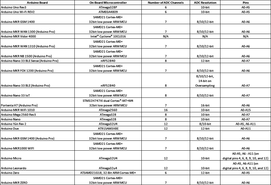
Arduino boards use different AVR/SAMD/SAM microcontrollers. Most of these microcontrollers have at least six ADC channels that are typically multiplexed to a SAR ADC. The resolution of a built-in ADC may vary from one board to another, though the ADC on most of the boards has a 10-bit resolution at the very least.
The default voltage reference is always the operating voltage of the board, so the boards can “sense” the unipolar voltages from the ground (0V) to 5 or 3.3V. It’s also possible to set the voltage reference to pre-defined internal voltages or an external voltage source.
In some of the Arduino boards, the voltage reference for the analog-to-digital conversion can be set individually for each channel.
The sampling rate of the analog signal is set by pre-scaling the clock used by the on-board controller. The sampling frequency is always a factor of the clock frequency of the controller, where the factor is determined by the built-in pre-scaler.
For lower resolution (like 8-bit), the ADC may use a higher frequency to maximize the sampling rate.
The ADC features of different Arduino boards are summarized here.
Analog input using Arduino UNO
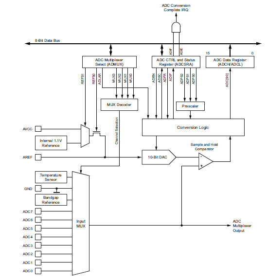
Arduino UNO has six analog input channels. The ATmega328P controller on UNO has a 10-bit successive approximation ADC, which is connected to an 8-channel analog multiplexer. This analog multiplexer allows eight, single-ended voltage inputs at pins of the Port A of the controller. The single-ended voltage input refers to the ground (0V).
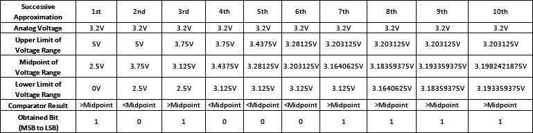
In SAR ADC, the comparator essentially compares the input voltage with the successively narrow range of voltages. At each step, the input voltage is compared to a voltage from an internal DAC (digital-to-analog converter) where the DAC output is the midpoint of the selected voltage range.
At each step, the approximation is stored in a successive approximation register (SAR). So, let’s suppose a voltage of 3.2 V is sampled from an analog signal. It’s first compared to the 2.5 V (midpoint of 0 and 5V).
- Since 3.2 V is greater than 2.5 V, it will next be compared with 3.75 V (the midpoint of 2.5 and 5V).
- Since 3.2V is less than 3.75 V, it will next be compared with 3.125 V (the midpoint of 2.5 and 3.75V), and so on.
As SAR ADC on ATmega328P has a 10-bit resolution, the input voltage is successively approximated 10 times to get a 10-bit digital reading. However, if it was an 8-bit SAR ADC, it would have taken eight successive approximations to get the 8-bit digital value, and so on.
In each successive approximation, one bit of the digital value is obtained starting from MSB to LSB (this means that in the first approximation, one obtains the MSB of the digital value, and in the next approximation, the bit next to the MSB is obtained). If in a successive approximation, the input voltage is greater than the midpoint of the selected voltage range, the obtained bit is 1. If the input voltage is less than the midpoint of the selected voltage range, the obtained bit is 0.
As the ADC has a 10-bit resolution, the output digital reading can vary from 0 to 1023 (2^10).
Taking the example of 3.2V, with 5V reference on a 10-bit SAR ADC, the successive approximations can be summarized here.
If comparing this with the equation of a standard, single-ended ADC conversion, the results are:
ADC = (VIN/VREF) * 1024
ADC = (3.2V/5V) * 1024
= 655.36 = 655 or (b1010001111)
The ADC has a 7-bit pre-scaler and may use 1/2, 1/4, 1/8, 1/16, 1/32, 1/64, or 1/128 of the clock frequency from the controller. The successive approximation circuit requires a clock frequency of 50 to 200 kHz. As the controller clocks by a 16 MHz crystal, even if a 1/128 pre-scaling is used for the sampling input voltage, the clock frequency of ADC is 125 kHz.
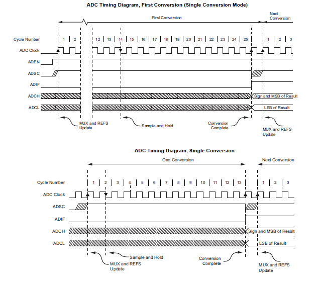
From the ADC timing diagrams, it’s possible to see that the ADC takes 25 ADC clock cycles for the first conversion and 13 ADC clock cycles for the normal, single-ended conversions. This means that if 1/128 pre-scaling is selected, it will take 200 microseconds (1/125KHz *25) for the first sample and 104 microseconds (1/125KHz *13) for the other readings.
For the auto-triggered conversions, the ADC takes 13.5 clock cycles (108 microseconds for a conversion). For the other pre-scaler, this conversion time must be even low. Typically, this ADC takes 65 to 260 microseconds for conversion, with the sampling analog inputs at a rate of up to 15k SPS (Samples Per Second).
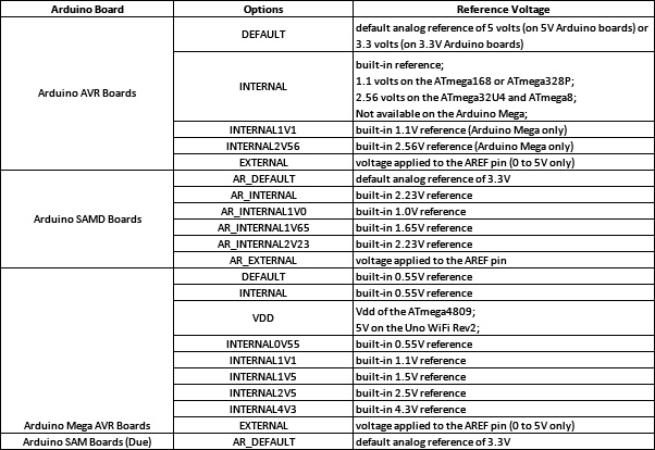
The default voltage reference is 5V. Other voltage references available on Arduino boards are listed in this table.
The ATmega328P has the following internal registers, which are associated with the functioning of the ADC.
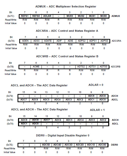
Before starting a conversion, the first voltage reference and the analog channel must be selected by setting an ADMUX register. To enable the ADC, the ADEN bit of the ADCSRA register must be set.
To start the conversions, after the ADC is enabled, the ADSC bit of the ADCSRA register also has to be set. The first conversion takes 25 ADC clock cycles while normal conversions take 13 ADC clock cycles. When a conversion is complete, the ADIF bit of the ADCSRA register is set (check the timing diagram of ADC) and the ADSC bit is cleared.
When the ADIF is set, the ADC data registers — and both the ADCL and ADCH are updated. The value of these registers must be retrieved when the ADIF is set to get the digital reading of the analog signal.
The bits ADPS2:0 of ADCSRA register are used to select the pre-scaler and determines the division factor between the system clock frequency and the input clock to ADC. The ADLAR bit of the ADMUX register determines how the ADC data registers (ADCL and ADCH) and are populated.
If the ADATE bit of the ADCSRA register is set, the auto-triggering of the ADC is enabled. In this case, the source which triggers the ADC conversion is determined by the ADTS2:0 bits of the ADCSRB register. The source of the trigger can be a timer/counter, external interrupt, or analog comparator.
The analogRead() function
For sensing the analog voltage from a sensor (or any source), the analogRead() function is used.
This function has the following source code:
In the analogRead() function, the first analog input channel must be selected according to the argument passed to the function. Then, the ADMUX and ADCSRB registers are passed values. The function tracks the ADSC bit of the ADCSRA register in a loop. Whenever the bit is set, it reads the values that are updated in ADCL and ADCH registers.
The function returns the value of the ADCL and ADCH registers as an integer number. The function has this syntax:
analogRead(pin)
It takes only one argument, which is a valid pin number where the analog input is expected. It returns the analog reading that may range from 0 to 1023 for a 10-bit resolution, or 0 to 4095 for a 12-bit resolution. Therefore, it must be assigned to a variable that can store the retrieved analog reading. The value obtained in the variable can then be used to plot the analog signal or to make a decision according to a user-defined program.
The analogReference() function
It’s possible to set a different voltage reference for ADC when using Arduino. By default, the voltage reference is always the operating voltage of the board. The voltage reference can be changed or set by using the analogReference() function.
This function has the following source code:
The function has the following syntax:
analogReference(type)
This function takes a single argument, which is an option for the voltage reference. The options that can be passed onto this function for different Arduino boards are already mentioned in the voltage reference table above. This function returns nothing.
The first few readings from the analogRead() may not be accurate when changing the analog reference. So, if the analogReference() function is called, the first few readings returned by the analogRead() function must be ignored in the user-defined program.
If the external voltage is set as an analog reference, it should never be less than 0V (bipolar voltages are not allowed on the analog pins) and it should not be greater than 5V (overvoltage can damage the pin or even the onboard controller).
An internal resistor of 32K is connected at the AREF pin. To set an external voltage as the reference, it should be supplied through an external resistor. The external resistor will form a voltage divider with the internal resistor at the AREF pin and the voltage reference can be set safely without concern of damaging the pin or the controller.
The analogReadResolution() function
The MKR, Due, and Zero boards have multiple resolution options for the analog-to-digital conversion. The default resolution is a 10-bit. However, lower or higher resolutions (up to 32) can be used on these boards. The resolution of the ADC can be changed by the analogReadResolution() function.
This function has the following syntax:
analogReadResolution(bits)
The argument bits determine the resolution of the analog reading returned by the analogRead() function. It can take any value from 1 to 32. It should be noted that in setting the resolution higher than 12, the approximations can suffer. Ideally, stick to 8-bit, 10-bit, or 12-bit resolutions unless there’s some strict demand to choose a higher resolution.
If a resolution is set that the board is incapable of, the analogRead() will return a reading with the highest resolution possible on that board, with padded zeros for the extra resolution. Similarly, if a lower resolution is set that’s beyond the capability of the board, the analogRead() will return a reading with the lowest resolution possible on that board — with the discarded LSB bits to match the selected resolution.
Potentiometer-controlled LED blink rate recipe
In this recipe, we will sense the analog voltage with the help of a potentiometer and use the changing analog voltage to alter the blink duration of an LED.
Components required
1. Arduino UNO x1
2. LED x1
3. 330 Ohms Resistor x1
4. Pot 10K/100K x1
5. Breadboard x1
6. Male-to-Male Jumper Wires or Connecting Wires
Circuit connections
First, connect the digital I/O pin 5 from Arduino UNO with the anode of the LED. Next, connect the cathode of the LED with a series resistor of 330 Ohms and ground the other terminal of the resistor.
Take the potentiometer and connect its fixed-end terminals 1 and 3 with the ground and 5V, respectively. Connect the variable-end terminal 2 of the pot to the analog input A5 of the Arduino UNO. The DC supply voltage and the ground can be given to the circuit from the 5V power pin and one of the ground pins of the Arduino UNO.
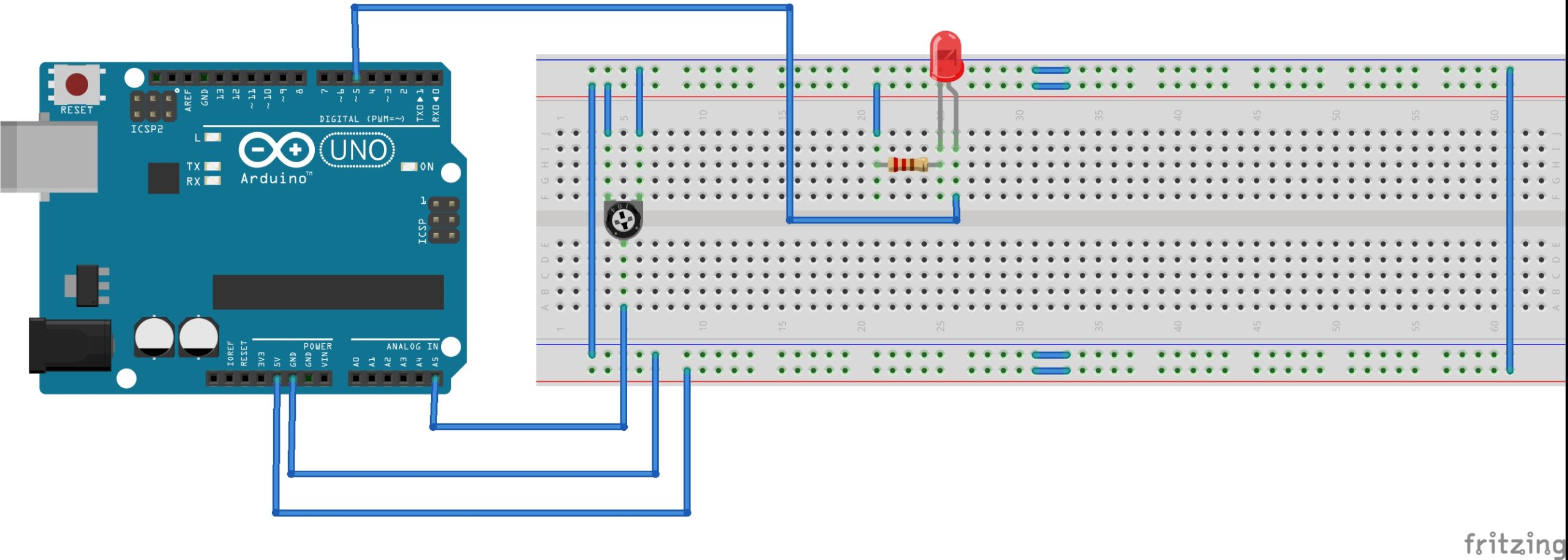
Circuit diagram

Arduino Sketch
int sensorPin = A5;
int ledPin = 5;
int analogVal = 0;
void setup() {
pinMode(ledPin, OUTPUT);
}
void loop() {
analogVal = analogRead(sensorPin);
digitalWrite(ledPin, HIGH);
delay(analogVal);
digitalWrite(ledPin, LOW);
delay(analogVal);
}
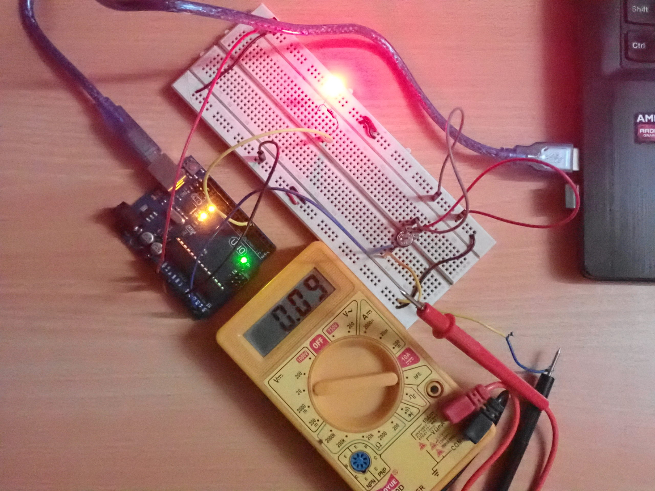
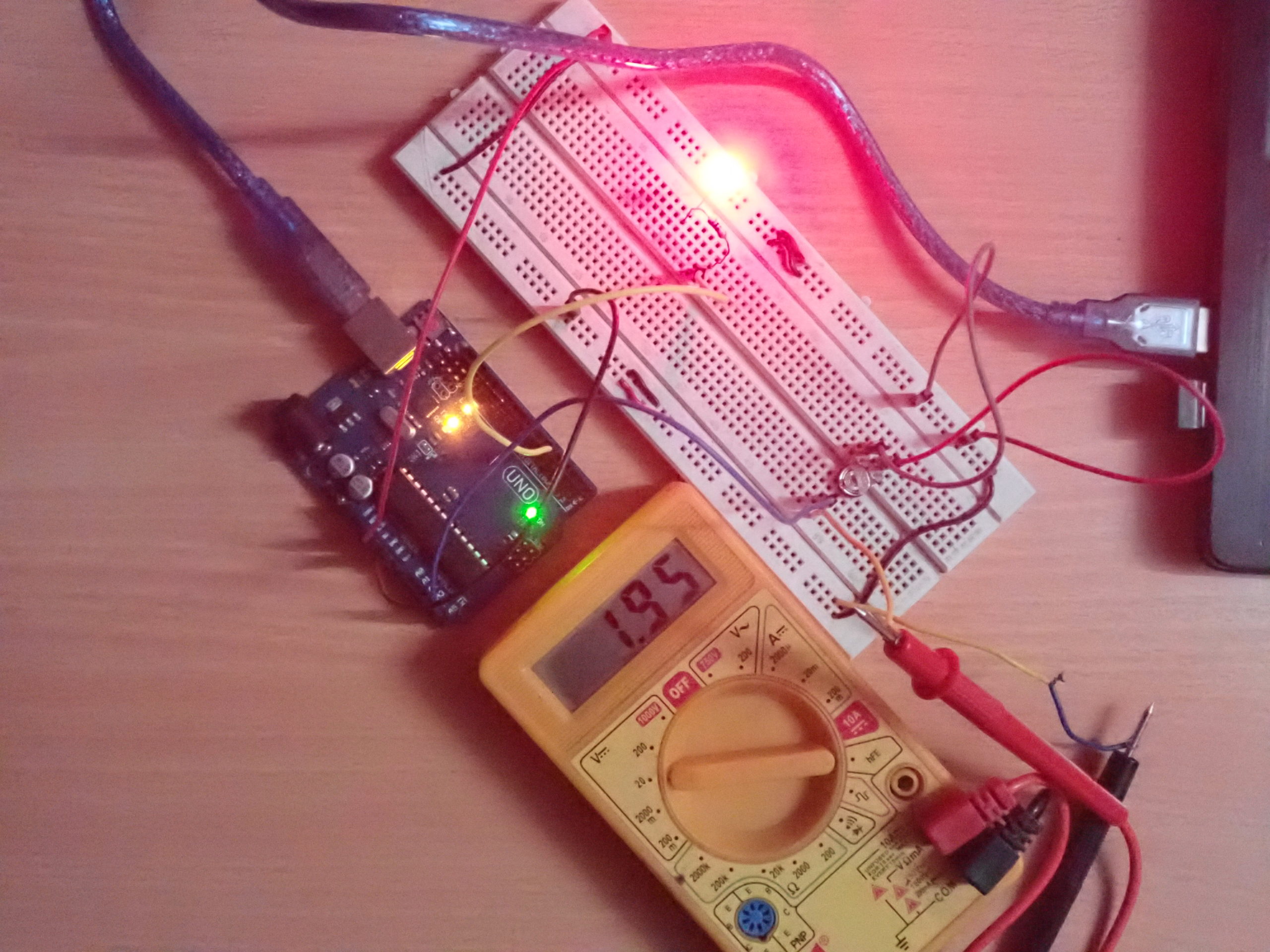
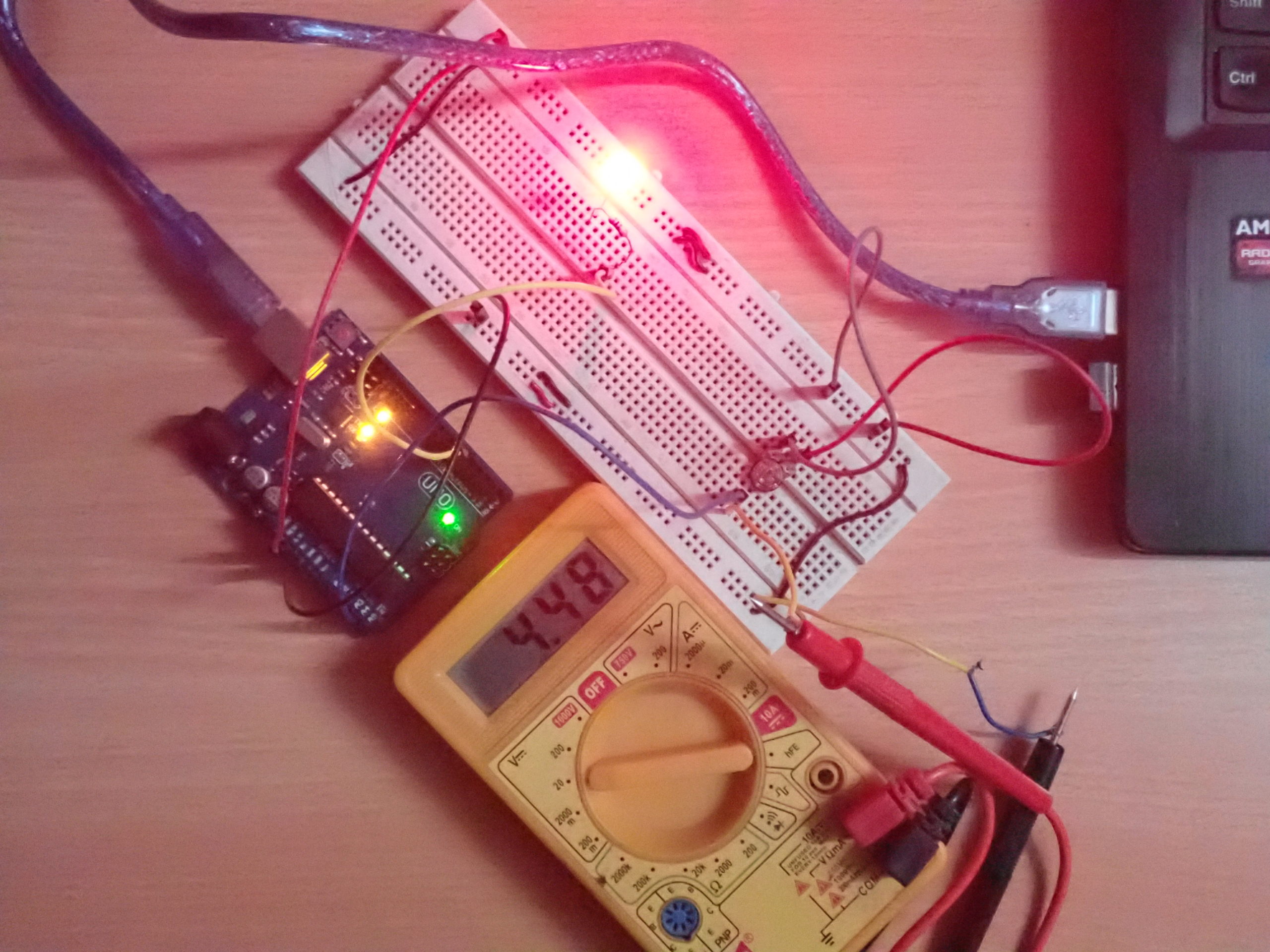
How the project works
The circuit is designed to change the blink rate of the LED by sensing the voltage from a trimmer potentiometer. The variable end of the trimmer is connected to the A5 pin of the UNO, while its fixed-ends are connected with the ground and VCC (5V DC).
The analog voltage at the variable-end of the trimmer can be varied between 0 and 5V by rotating the knob of the trimmer. This voltage is applied to the analog input A5 of the Arduino UNO.
The analog voltage from the trimmer is read using the analogRead() function, which returns a value between 0 and 1023. The analog reading is used as a delay interval in milliseconds between switching the LED ON and OFF. When the knob of the potentiometer is close to the fixed-end terminal that’s connected to the ground, the low analog voltage is applied to the analog pin A5 and the low analog reading is recorded.
So, the delay interval between switching the LED ON/OFF remains between 40 to 70 milliseconds and the LED blinks at a higher rate. When the knob is rotated close to the fixed-end terminal that’s connected to the VCC, the high analog voltage is applied to the A5 pin and the high analog reading is recorded. The delay interval between switching the LED ON/OFF remains between 800 and 1000 milliseconds, and the LED blinks at a lower rate.
Programming guide
The three global variables are defined per:
- The sensorPin to indicate the analog input pin
- The ledPin to indicate digital pin where the LED is interfaced
- The analogVal to store the analog reading
The sensorPin is assigned a value of A5 where the trimmer is interfaced, and the ledPin is assigned a value of 5 where the LED is interfaced.
In the setup() function, the pin where the LED is interfaced is configured as the output using the pinMode() function. In the loop() function, the analog reading at pin A5 is obtained using the analogRead() function and it’s stored in the analogVal variable.
The LED is interfaced such that pin 5 should serve as the current source to it. Pin 5 is set to HIGH using the digitalWrite() function so that the LED starts glowing. A delay equal to the analog reading is provided by calling the delay() function, with the analogVal as the argument. The LED is then switched OFF by setting pin 5 to LOW using the digitalWrite() function.
Again, a delay equal to the analog reading is provided by calling the delay() function with the analogVal as the argument.
Potentiometer-controlled LED fading recipe
In this recipe, we will sense the analog voltage using a potentiometer and the changing analog voltage to fade an LED.
Requirements
Here, the components required, circuit connections, and circuit diagram are all the same as in the above-mentioned, “Potentiometer-controlled LED blink rate recipe.”
Arduino sketch
int sensorPin = A5;
int ledPin = 5;
int analogVal = 0;
void setup() {
pinMode(ledPin, OUTPUT);
}
void loop() {
analogVal = analogRead(sensorPin);
analogWrite(ledPin, analogVal/4);
}
How the project works
This circuit is designed to fade an LED using a potentiometer. The analog voltage is applied at the A5 pin of the Arduino via a trimmer potentiometer. This analog voltage is read using the analogRead() function.
This function returns a value between 0 to 1023. This value is divided by four to obtain a value between 0 and 255, and then it is passed as the duty-cycle argument in the analogWrite() function. The analogWrite() function produces a PWM signal at pin 5 where the LED is connected.
- When the analog input at the A5 pin is low, the analog reading remains between 40 and 50. When this reading (after a factor of four) is passed as the duty cycle, a PWM wave of the low duty cycle is generated at pin 5 of the UNO and the LED remains faded.
- When the analog input at the A5 pin is high, the analog reading remains between 800 to 1000. When this reading (after a factor by four) is passed as the duty cycle, a PWM wave of the high-duty cycle is generated at pin 5 of the UNO and the LED gets illuminated.
Programming guide
The three global variables are defined as follows:
- The sensorPin to indicate the analog input pin
- The ledPin to indicate digital pin where the LED is interfaced
- The analogVal to store the analog reading.
The sensorPin is assigned a value of A5 where the trimmer is interfaced and the ledPin is assigned a value of 5 where the LED is interfaced.
In the setup() function, the pin where the LED is interfaced is configured as output by using the pinMode() function. In the loop() function, the analog reading at the A5 pin is obtained using the analogRead() function and it’s stored in the analogVal variable.
The LED is interfaced such that pin 5 should serve as the current source to it. A PWM wave is generated at pin 5 by calling the analogWrite() function in which the duty cycle is set to the analog reading (factored by four).
The analog reading is factored by four and the value of the duty cycle should be between 0 and 255, while the analog reading can be between 0 and 1023.
As the analog voltage at the A5 pin of UNO increases, the duty cycle increases and the LED will become more illuminated. As the analog voltage at the A5 pin of UNO decreases, the duty cycle decreases and the LED will fade.
In the next tutorial, we will discuss interfacing an RGB LED using Arduino.
You may also like:


Filed Under: Arduino, Tutorials

Questions related to this article?
👉Ask and discuss on Electro-Tech-Online.com and EDAboard.com forums.
Tell Us What You Think!!
You must be logged in to post a comment.